Before the refrigerator became a normal part of any kitchen, those with enough money to throw around could get an icebox, which used melting ice to cool food and drinks in a second compartment. As refrigerators became available for sale in the 1920s, this created somewhat awkward transition models, like the 1924 Frigidaire B-9 that [David Allen] recently got offered for a restoration. This was part of the restoration of a 1926 house, which foresaw putting this venerable unit back into operation.
As [David] explains, this refrigerator was still in use until about 1970 when it broke down, and repairs proved tricky. Clearly, the fault wasn’t that severe as [David] got it working again after a number of small repairs and a lot of maintenance. The running unit with its basic elements can be seen purring away in the completion video, with the journey to get there covered in a video series starting with the first episode.
What’s fascinating is that during this aforementioned transition period, the vapor compression electric cooling system was an optional extra, meaning that the basic layout is still that of an icebox. Correspondingly, instead of ice in the ice compartment, you find the low-side float evaporator, with the basement section containing the condensing unit, motor, and compressor. The temperature sensor is also a miracle of simplicity, using bellows that respond to the temperature and thus volume of the evaporator coolant, which trigger a switch that turns on the compressor.
Despite a hundred years having passed since this refrigerator was constructed, at its core it works exactly the same as the unit we have in our kitchens today, albeit with higher efficiency, more electronics, and with the sulfur dioxide refrigerant replaced with something less toxic to us humans.
Carbon fiber (CF) has attained somewhat of a near-mystical appeal in consumer marketing, with it being praised for being stronger than steel while simultaneously being extremely lightweight. This mostly refers to weaved fibers combined with resin into a composite material that is used for everything from car bodies to bike frames. This CF look is so sexy that the typical carbon-fiber composite weave pattern and coloring have been added to products as a purely cosmetic accent.
More recently, chopped carbon fiber (CCF) has been added to the thermoplastics we extrude from our 3D printers. Despite lacking clear evidence of this providing material improvements, the same kind of mysticism persists here as well. Even as evidence emerges of poor integration of these chopped fibers into the thermoplastic matrix, the marketing claims continue unabated.
As with most things, there’s a right way and a wrong way to do it. A recent paper by Sameh Dabees et al. in Composites for example covered the CF surface modifications required for thermoplastic integration with CF.
Carbon Fibers
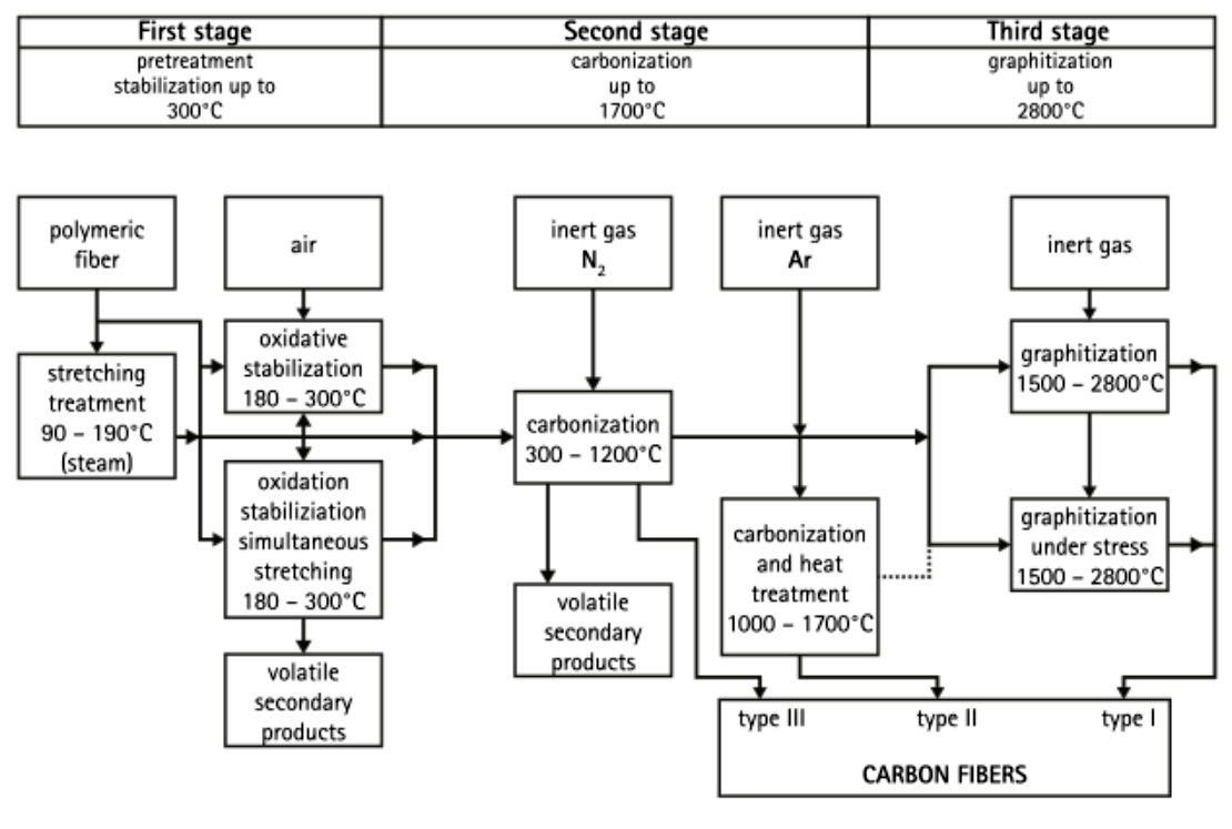
There are a number of ways to produce CF, often using polyacrylonitrile, rayon, or pitch as the feedstock. After spinning this precursor into a suitable filament, heating induces carbonization and produces the carbon fiber.
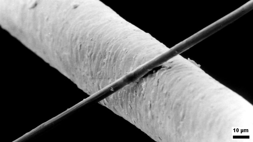
Schematic representation of carbon fiber preparation from polyacrylonitrile.A 6 μm diameter carbon filament, compared to 50 μm diameter human hair. (Source: Wikimedia)
Following this process, the CF is typically in the form of a few micrometer-thick fiber that is essentially pure carbon. To create a structural interface between the CF and the polymer of a composite material, some kind of process has to take place that creates this interface.
The fundamental difference between thermoset and thermoplastic polymers is that thermoset polymers are reacting in the mold as it sets, providing an environment in which the epoxy precursor and hardener can interact with the normally not chemically very reactive CF to form covalent bonds.
In comparison, thermoplastic polymers are already finalized, with covalent bonds between thermoplastics and CF unlikely. This means that the focus with CF-reinforced thermoplastics is mostly on weaker, non-covalent interactions, such as Van der Waals forces, pi-interactions and hydrogen bonds. Each of these interactions is further dependent on whether the thermoplastic is compatible, such as the presence of aromatic rings for pi-interactions.
Making It Stick
With those challenges in mind, how can thermoplastics be coaxed into forming a significant interface with CF? As noted in the earlier cited work by Sameh Dabees et al., there is no single surface treatment for CF that would work for every thermoplastic polymer, as a logical result of the limitations imposed by the available non-covalent interactions.
Carbon fiber in PLA after FDM printing, showing clear voids. (Credit: I built a thing, YouTube)
One way to prepare the CF is by applying a coating to the fiber, called a sizing. By applying a sizing to the fiber that is compatible with the target thermoplastic, the interface with the bulk material is expected to improve. In one cited study involving a polyamide-acid sizing for polyimide bulk material, this coating created an approximately 85 nm interface, with an interfacial shear strength increased by 32.3%. In another study targeting CF-PEEK, this had a polyimide-based, water-soluble sizing applied that also significantly improved the shear strength.
Of course, this sizing has to actually adhere to the CF, lest it simply vanishes into the bulk thermoplastic material. This is a problem that is easily observable in FDM-printed thermoplastic polymers as distinct voids around the CF where the bulk polymer pulled away during crystallization, and no interface formed. Obviously, these voids create a weak point instead of strengthening the material.
Fiber Modding
Although CF is often confused with carbon nanotubes, it does not have the rigidly ordered structure that they do. Instead it has a graphite structure, owing to the way that they are produced, meaning sheets of graphite placed together in a disordered fashion. Despite this, the external surface is still smooth, which is where the chemical inertness comes from. Combined with the lack of reactivity from the side of thermoplastics, this highlights the need for something to bridge the gap.
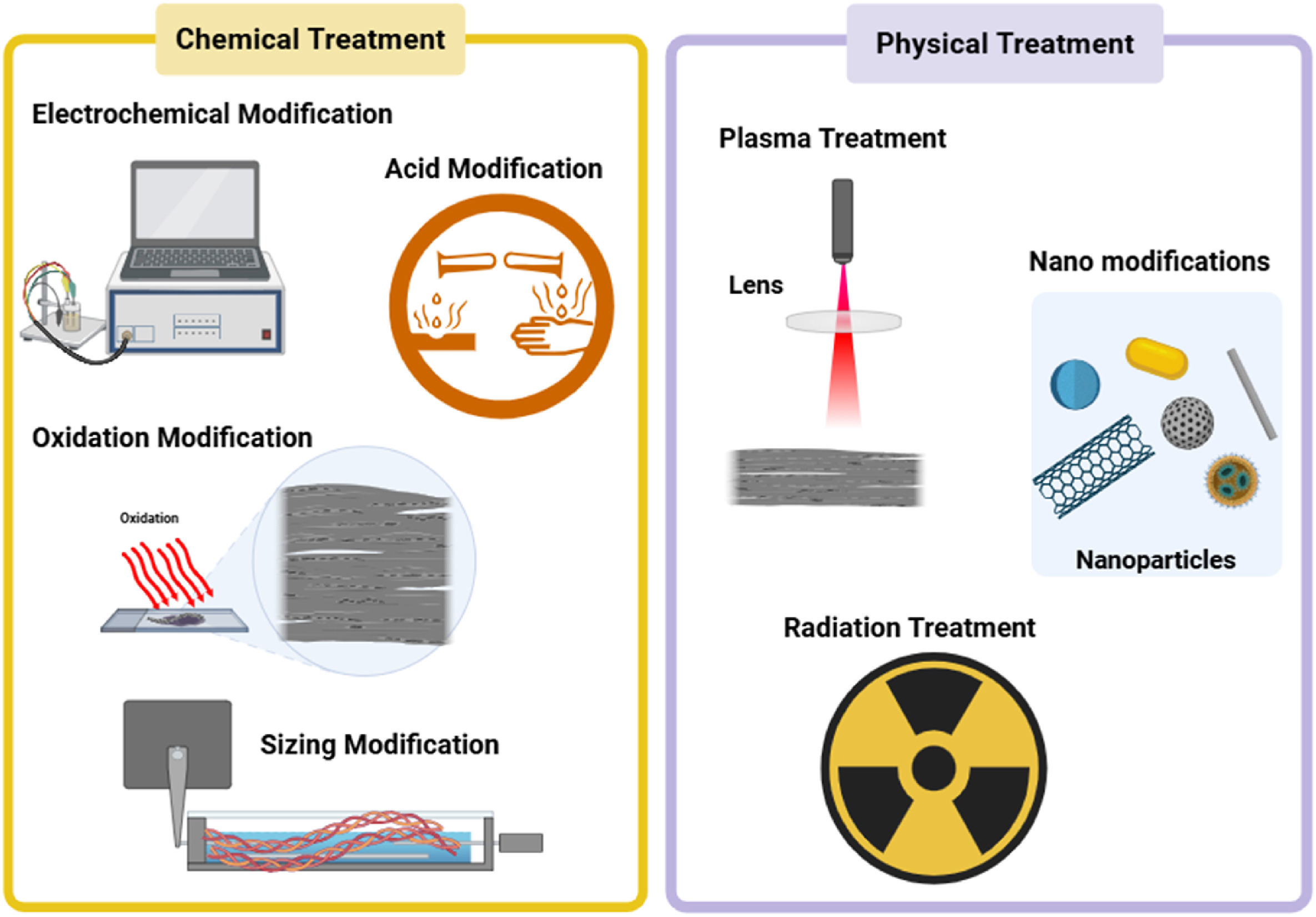
Various carbon fiber surface modification methods. (Credit: Dabees et al., 2025, Composites)
The review paper by Dabees et al. covers the most common types of surface treatments, with the above graphic providing a summary of the methods. Perhaps one of the most straightforward methods is the coating of the CF with an epoxy, thus shifting the interface from CF-thermoplastic to thermoset-thermoplastic. This kind of hybrid approach shows promising results, but is also cumbersome and not a universal fix.
Note that virtually all research here is focused on thermoplastic polymers like polycarbonate and PEEK, as these are most commonly used in industrial and medical settings. Yet even within that more limited scope the understanding of the exact effects of these modifications remains poorly investigated. Much of this is due to how hard it is to characterize the effects of one treatment when you take all other variables into account.
Perhaps most frustrating of all is how hard it is to research this topic considering the scale of the CF surface and the miniscule thickness of the CF-polymer interface. Relying on purely mechanical tests to quantify the impact is then tempting, but ultimately leaves us without a real understanding of why one method seems to work better than another.
Vibes Vs Science
The overall conclusion that we draw from this particular review paper is that although we know that composite materials can often provide improvements, in the case of thermoplastic-CF composites we realize that our understanding of the fundamentals is still rather lacking.
Outside of the less mainstream world of industrial and medical settings, CF is now widely being added to thermoplastic polymers, primarily in the form of filaments for FDM 3D printers. Without detailed information on whether the manufacturers of these filaments perform any kind of CF surface modification, it is very hard to even compare different CF-polymer filaments like this, even before taking into account individual FDM printer configurations and testing scenarios.
Considering that CF has for a few years now been identified as a potential carcinogen akin to asbestos, this raises the question of whether we really want to put CF and particularly the very small chopped carbon fibers into everything around us and thermoplastics in particular. When the empirical evidence available to us today shows that any mechanical improvements are not due to a solid CF-polymer interface, and any potential carcinogenic risks still years into the future of becoming clear, then the logical choice would be to hold back on CF-thermoplastics until we gain a better understanding of the benefits and risks.
Over the past years, the author of the cURL project, [Daniel Stenberg], has repeatedly complained about the increasingly poor quality of bug reports filed due to LLM chatbot-induced confabulations, also known as ‘AI slop’. This has now led the project to suspend its bug bounty program starting February 1, 2026.
Examples of such slop are provided by [Daniel] in a GitHub gist, which covers a wide range of very intimidating-looking vulnerabilities and seemingly clear exploits. Except that none of them are vulnerabilities when actually examined by a knowledgeable developer. Each is a lengthy word salad that an LLM churned out in seconds, yet which takes a human significantly longer to parse before dealing with the typical diatribe from the submitter.
Although there are undoubtedly still valid reports coming in, the truth of the matter is that the ease with which bogus reports can be generated by anyone who has access to an LLM chatbot and some spare time has completely flooded the bug bounty system and is overwhelming the very human developers who have to dig through the proverbial midden to find that one diamond ring.
We have mentioned before how troubled bounty programs are for open source, and how projects like Mesa have already had to fight off AI slop incidents from people with zero understanding of software development.
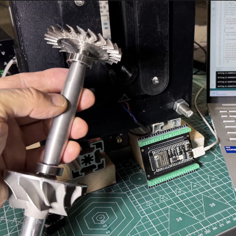
Although jet engines are theoretically quite simple devices, in reality they tread a fine line between working as intended and vaporizing into a cloud of lethal shrapnel. The main reason for this is the high rotational speed of the rotors, with any imbalance due to poor manufacturing or damage leading to undesirable outcomes. It’s for this reason that [AlfMart CNC Garage] on YouTube decided to spend some quality time building a balancer for his DIY RC turbine project and making sure it can prevent such a disaster scenario.
In the previous part of the series the turbine disc was machined out of inconel alloy, as the part will be subjected to significant heat as well when operating. To make sure that the disc is perfectly balanced, a dynamic balancing machine is required. The design that was settled on after a few failed attempts uses an ADXL335 accelerometer and Hall sensor hooked up to an ESP32, which is said to measure imbalance down to ~1 mg at 4,000 RPM.
A big part of the dynamic balancing machine is the isolation of external vibrations using a bearing-supported free-floating structure. With that taken care of, this made measuring the vibrations caused by an imbalanced rotor much easier to distinguish. The ESP32 is here basically just to read out the sensors and output the waveforms to a connected PC via serial, with the real work being a slow and methodical data interpretation and balancing by hand.
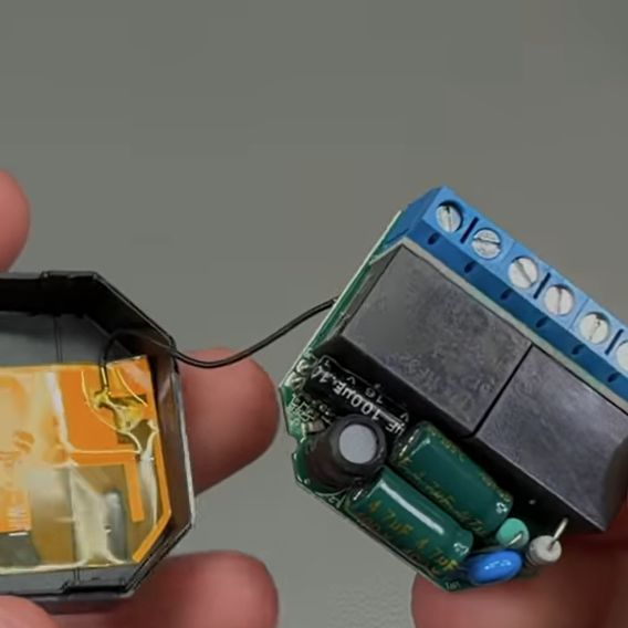
In [Big Clive]’s recent grab bag of tat ordered from Chinese commerce platforms, there were two touch light control boxes that can turn any ungrounded conductive surface into a mains load dimmer control. Of course, the primary reason for the purchase was a teardown, and a teardown we got.
These unassuming little boxes are built around the Tontek TT6061A, listed as a ‘touch dimmer’, which uses a triac to control the output current. There are four levels, ranging from off to full brightness, before the next touch event turns the output off again.
With the output off, [Clive] measured 0.7 W power usage. After popping open the plastic enclosure, the circuitry turned out to largely follow the recommended application circuit from the datasheet — as can be seen in the above screenshot — with apparently a few cost optimizations, in the form of omitted diodes and a capacitor.
The problem with these devices is that they are only really suitable for dimming low-power resistive loads like incandescent lights, with LED lights likely requiring the unpopulated capacitor spot on the PCB to be populated to tweak the chip’s triac timing, among other changes. There are also the slight issues with no real concern with them radiating EMI, and the exciting possibility of getting shocked at mains voltage without at least a class-Y capacitor installed.
Perhaps using a capacitive touch controller instead that works through plastic, for example, isn’t such a crazy alternative here, especially since they’re not really much more expensive and less likely to shock you. Want to create your own triac designs? We have just the post to get you started.
When you’re testing or debugging some mains-powered gear, plugging it directly into the outlet can often be an exciting proposition. If such excitement is not really your thing, you can opt for an isolation transformer and other types of safeties. In the case of [Michał Słomkowski], he opted to take a few steps further by modding a vintage East-German isolating variac with a broken amp meter into an isolated AC/DC power supply and testing station.
The core is formed by the isolated variable transformer, to which a configurable DC output section, a current limiter and digital voltage and current read-outs were added. This enables a variable AC output of 0 – 330 VAC and 0 – 450 VDC on their respective terminals, with the incandescent light bulb providing an optional current limiter.
In its final configuration [Michał] has been using the device for the past four years now for a range of tasks, including the simulating of various undesirable mains power conditions, varying the speed of an old Soviet-era drill, powering vacuum tube devices, capacitor reforming and of course running 100-120 VAC devices from e.g. the US.
As far as feature set goes, we have to admit that it is an impressive device, indeed. Although some parts of it are clearly playing it fast and loose with best practices, with [Michał] admitting to not being an electrician, it was clearly engineered well enough to survive a few years of use, something which cannot be said for even professional laboratory equipment these days.
Researchers at Stanford University recently came up with an interesting way (Phys.org summary) to create patterns and colors that emerge when a polymer is exposed to water. Although the paper itself is sadly paywalled with no preprint available, it’s fairly easily summarized and illustrated with details from the Supplementary Data section. The polymer used is poly(3,4-ethylenedioxythiophene) polystyrene sulfonate (PEDOT:PSS), which when exposed to an electron beam (electron-beam lithography) undergoes certain changes that become apparent when said water is added.
The polymer is hygroscopic, but the electron beam modifies the extent to which a specific area swells up, thus making it possible to create patterns that depend on the amount of electron beam exposure. In order to ‘colorize’ the polymer, complex cavities are created that modify the angular distribution of light, as illustrated in the top image from the Supplemental Data docx file.
By varying the concentration of IPA versus water, the intermediate swelling states can be controlled. Although this sounds pretty advanced, if you look at the supplementary videos that are already sped up a lot, you can see that it is a very slow process. Compared to an octopus and kin whose ability to alter their own skin texture and coloring is legendary and directly controlled by their nervous system, this isn’t quite in the same ballpark yet, even if it’s pretty cool to watch.
After having been sent a vacuum fluorescent display (VFD) based clock for a review, [Anthony Francis-Jones] took the opportunity to explain how these types of displays work.
Although VFDs are generally praised for their very pleasant appearance, they’re also relatively low-power compared to the similar cathode ray tubes. The tungsten wire cathode with its oxide coating produces the electrons whenever the relatively low supply voltage is applied, with a positively charged grid between it and the phosphors on the anode side inducing the accelerating force.
Although a few different digit control configurations exist, all VFDs follow this basic layout. The reason why they’re also called ‘cold cathode’ displays is because the cathode doesn’t heat up nearly as hot as those of a typical vacuum tube, at a mere 650 °C. Since this temperature is confined to the very fine cathode mesh, this is not noticeable outside of the glass envelope.
While LCDs and OLED displays have basically eradicated the VFD market, these phosphor-based displays still readily beat out LCDs when it comes to viewing angles, lack of polarization filter, brightness and low temperature performance, as LC displays become extremely sluggish in cold weather. Perhaps their biggest flaw is the need for a vacuum to work, inside very much breakable glass, as this is usually how VFDs die.
After the swivel by Helium Inc. towards simply running distributed WiFi hotspots after for years pushing LoRaWAN nodes, much of the associated hardware became effectively obsolete. This led to quite a few of these Nebra LoRa Miners getting sold off, with the [Buy it Fix it] channel being one of those who sought to give these chunks of IP-67-rated computing hardware a new life.
Originally designed to be part of the Helium Network Token (HNT) cryptocurrency mining operation, with users getting rewarded by having these devices operating, they contain fairly off-the-shelf hardware. As can be glanced from e.g. the Sparkfun product page, it’s basically a Raspberry Pi Compute Module 3+ on a breakout board with a RAK 2287 LoRa module. The idea in the video was to convert it into a Meshcore repeater, which ought to be fairly straightforward, one might think.
Unfortunately the unit came with a dead eMMC chip on the compute module, the LoRa module wasn’t compatible with Meshcore, and the Nebra breakout board only covers the first 24 pins of the standard RPi header on its pin header.
The solutions involved using a µSD card for the firmware instead of the eMMC, and doing some creative routing on the bottom of the breakout board to connect the unconnected pins on the breakout’s RPi header to the pins on the compute module’s connector. This way a compatible LoRa module could be placed on this header.
Rather than buying an off-the-shelf LoRa module for the RPi and waiting for delivery, a custom module was assembled from an eByte E22 LoRa module and some stripboard to test whether the contraption would work at all. Fortunately a test of the system as a Meshcore repeater showed that it works as intended, serving as a pretty decent proof-of-concept of how to repurpose those systems from a defunct crypto mining scheme into a typical LoRa repeater, whether Meshcore or equivalent.
Although already having entered the territory of ‘retro gaming’, the Sony PlayStation 3 remains a notoriously hard to emulate game console. Much of this is to blame on its unique PowerPC-based Cell processor architecture, which uses a highly parallel approach across its asymmetric multi-core die that is very hard to map to more standard architectures like those in today’s x86 and ARM CPUs. This makes it even more amazing that the RPCS3 emulator team has now crossed the 70% ‘playable’ threshold on their compatibility list.
This doesn’t mean that you can fire up these games on any purported ‘gaming system’, as the system requirements are pretty steep. If you want any kind of enjoyable performance the recommended PC specifications feature an Intel 10th generation 6-core CPU, 16 GB of dual-channel RAM and a NVIDIA RTX 2000 or AMD RX 5000 series GPU or better.
It should be noted here also that the ‘playable’ tag in the compatibility list means that the game can be completed without game breaking glitches. Performance remains an issue, with very creative optimizations through e.g. the abuse of x86 SIMD instructions remaining the topic of research by the emulator developers. Yet as original PS3 hardware gradually becomes less available, the importance of projects like RPCS3 will become more clear.
Well there’s your problem. (Credit: Mark Funeaux, YouTube)
Akin to the razor-and-blades model, capsule-based coffee machines are an endless grind of overpriced pods and cheaply made machines that you’re supposed to throw out and buy a new one of, just so that you don’t waste all the proprietary pods you still have at home. What this also means is a seemingly endless supply of free broken capsule coffee makers that might be repairable. This is roughly how [Mark Furneaux] got into the habit of obtaining various Nespresso VertuoLine machines for attempted repairs.
The VirtuoLine machines feature the capsule with a bar code printed on the bottom of the lip, requiring the capsule to be spun around so that it can be read by the optical reader. Upon successful reading, the code is passed to the MCU after which the brewing process is either commenced or cruelly halted if the code fails. Two of the Vertuo Next machines that [Mark] got had such capsule reading errors, leading to a full teardown of the first after the scanner board turned out to work fine.
Long story short and many hours of scrubbed footage later, one machine was apparently missing the lens assembly on top of the photo diode and IR LED, while the other simply had these lenses gunked up with spilled coffee. Of course, getting to this lens assembly still required a full machine teardown, making cleaning it an arduous task.
Unfortunately the machine that had the missing lens assembly turned out to have another fault which even after hours of debugging remained elusive, but at least there was one working coffee machine afterwards to make a cup of joe to make [Mark] feel slightly better about his life choices. As for why the lens assembly was missing, it’s quite possible that someone else tried to repair the original fault, didn’t find it, and reassembled the machine without the lens before passing the problem on to the next victim.
Espressif has unveiled its latest major chip in the form of the ESP32-E22. Officially referred to as a Radio Co-Processor (RCP), it’s intended to be used via its PCIe 2.1 or SDIO 3.0 host interface to provide wireless communications to an SoC or similar.
This wireless functionality includes full WiFi 6E functionality across all three bands, 160 MHz channel bandwidth and 2×2 MU-MIMO, making it quite a leap from the basic WiFi provided by e.g. the ESP32-S* and -C* series. There is also Bluetooth Classic and BLE 5.4 support, which is a relief for those who were missing Bluetooth Classic in all but the original ESP32 for e.g. A2DP sinks and sources.
The ESP32-E22 processing grunt is provided by two proprietary Espressif RISC-V CPU cores that can run at 500 MHz. At this point no details appear to be available about whether a low-power core is also present, nor any additional peripherals. Since the graphics on the Espressif PR article appear to be generic, machine-generated images – that switch the chip’s appearance from a BGA to an LQFP package at random – there’s little more that we can gather from there either.
Currently Espressif is making engineering samples available to interested parties after presumed vetting, which would indicate that any kind of public release will still be a while off. Whether this chip would make for an interesting stand-alone MCU or SoC along the lines of the -S3 or -P4 will remain a bit of a mystery for a bit longer.
How do you go about making a mirror with 128 segments, each of which can be independently angled? That was the question that a certain bloke over at [Time Sink Studio] found himself pondering on, to ultimately settle on a whole batch of mini-actuators bought through AliExpress. These stepper-based actuators appear to be akin to those used with certain Oppo smartphones with pop-up camera, costing less than half a dollar for a very compact and quite fast actuator.
The basic design is very much akin to a macro version of a micromirror device, as used in e.g. DLP projectors, which rely on a kinetic mirror mount to enable precise alignment. With the small actuators travelling up to 8 mm each, the mirrors can cover 73 mm at a distance of 4 meters from a wall.
With the required angle of the mirror being effectively just the application of the Pythagorean theorem, the biggest challenge was probably calibrating these linear motors. Since they’re open loop devices, they are zeroed much like the steppers on 3D printers, by finding the end limit and counting steps from that known point. This doesn’t make drift impossible, but for projecting light onto walls it’s clearly more than good enough.
Although arguably redundant on a typical computer keyboard, the idea of embedding small screens into the buttons on devices like audio production gear that often have so many buttons can make a lot of sense. As exemplified by devices with a UX that regularly degrades into scrolling through options on a tiny screen. This was basically the impetus for [Craig J Bishop] a few years ago to set out on a design project called the SoundSlabaudio sequencer/sampler/synthesizer and slab that would make those buttons much more functional.
Obviously, the right way to start the project is to bulk buy hundreds of 0.85″ 128×128 LCDs so that you’re firmly locked into that choice. Fortunately, it turned out that the most annoying part of this LCD was the non-standard 0.7 mm pitch on its flat flex cable (FFC). This was worked around with an PCB adapter milled out of some copper-clad FR-1, which gave it a convenient PMOD interface for straightforward hook-up to a Xilinx Artix-7 FPGA board.
The buttons themselves were designed as 3D printed key caps for the LCDs that clipped onto typical Cherry MX-style mechanical keys. This also revealed that the original FFCs were too short, so they had to be replaced with new FFCs, that also adapted it to a standard 0.5 mm pitch. With this a 4×4 button prototype board could be constructed for testing.
Since that prototype [Craig] has built a full-sized SoundSlab grid, with a custom FPGA board and HDMI input, of which a preview can be seen in the post, along with a promise by [Craig] to soon post the rest of the SoundSlab development.
Washington State’s House Bill 2321 is currently causing a bit of an uproar, as it seeks to add blocking technologies to 3D printers, in order to prevent them from printing “a firearm or illegal firearm parts”, as per the full text. Sponsored by a sizeable number of House members, it’s currently in committee, so the likelihood of it being put to a floor vote in the House is still remote, never mind it passing the Senate. Regardless, it is another chapter in the story of homemade firearms, which increasingly focuses on private 3D printers.
Also called ‘ghost guns‘ in the US, these can be assembled from spare parts, from kits, from home-made components, or a combination of these. While the most important parts of a firearm, like the barrel, have to be made out of something like metal, the rest can feature significant amounts of plastic parts, though the exact amount varies wildly among current 3D-printed weapons.
Since legally the receiver and frame are considered to be ‘firearms’, these are the focus of this proposed bill, which covers both additive and subtractive technology. The proposal is that a special firearms detection algorithm has to give the okay for the design files to be passed on to the machine.
This blocking feature would have to be standard for all machines sold or transferred in the state, with a special ‘preprint authentication’ handshake protocol required. The attorney general is here expected to create and maintain a database of the no longer legal firearm and parts designs for those without a requisite license.
Putting aside for a moment the ridiculousness of implementing such a scanning feature, even if it wouldn’t be child’s play to circumvent, it also barks up the wrong tree. Although in the most recent ruling pertaining to this topic in Bondi v. VanDerStok it was acknowledged that advances in 3D printing have made this worth considering from a legislative context, the main issue with ‘ghost guns’ comes still by far from kits and similar sources.
Based on this, it seems highly unlikely that HB 2321 will be put up for a vote, never mind get signed into law. Although 3D printed designs like the 9 mm x1 9 mm cartridge Urutau bullpup are apparently quite functional, it’s notable that its manufacturing involves many steps, many DIY store parts, and a bolt carrier manufactured from steel bar stock, not to mention a significant time investment. Trying to detect ‘firearm parts’ at any of these steps would seem to be a fool’s errand, even if privacy considerations were not an issue.
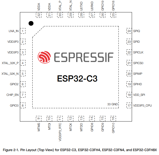
In an update video by [Hacker University] to an earlier video on ESP32-C3 Super Mini development boards that feature a Flash-less version of this MCU, the question of adding your own Flash IC to these boards is addressed. The short version is that while it is possible, it’s definitely not going to be easy, as pins including SPIHD (19) and SPICLK (22) and SPIQ (24) are not broken out on the board and thus require one to directly solder wires to the QFN pads.
Considering how sketchy it would be to have multiple wires running off to an external Flash IC, this raises many questions about the feasibility, as well as cost-effectiveness. Some in the comments to the video remark that instead you may as well swap the MCU with a version that does contain built-in Flash, but this is countered with the argument that a new ESP32-C3 Super Mini board with the right MCU costs as much as a loose MCU from your favorite purveyor of ICs.
Ultimately this lends some credence to calling these zero Flash Super Mini boards a ‘scam’, as their use cases would seem to be extremely limited and their Flash-less nature very poorly advertised.
ESP32-C3 reference implementation with external flash. (Credit: Espressif)
The fun part about world records is that anyone can take a swing at breaking them, which is what [Luke Maximo Bell] has been doing with the drone speed record for the past years, along with other teams in a friendly competition. After having some Aussie blokes previously smash the record with a blistering 626 km/h, the challenge was on for [Luke] and his dad to reclaim the title. This they did with the V4 of their quadcopter design, adding a range of improvements including new engines, new props and an optimized body to eek out more performance.
In the video we see these changes and the tests in detail. Interestingly, the simulations ran on the computer showed that the new body actually had to be larger, necessitating the use of a larger FDM printer. Fortunately a certain FDM 3D printer company sponsors just about everyone out there, hence the new design was printed on a Bambu Lab H2D, also making use of the dual extruder feature to print combined PETG/TPU parts.
It was also attempted to have a follow camera attached to a second FPV done in the form of a 360 degrees camera, but this turned out to be a bit too complex to get good shots, so this will have to be retried again.
In the end a new world record was set at an average of 657 km/h, which sets the stage for the next team to try and overtake it again. As for where the limit is, propeller airplanes have hit over 800 km/h, so there’s still quite a way to go before details like the sound barrier become a problem.
Part of any self-respecting Smart Home, smart relays are useful for switching and monitoring loads that do not plug into an outlet. This also makes them a lot more integrated, and thus, a long lifespan is very welcome. Unfortunately, the popular Shelly 2.5 smart relays seem to be having a bit of a design flaw as they’re dying in droves once their 2-year warranty period is up. The cause and repair are covered in a recent [VoltLog] video on YouTube.
As noted in the Shelly documentation for the device, it’s a very compact form factor device, with screw terminals, two relays, and three fairly large electrolytic capacitors sharing very little space with the rest of the components. The apparent flaw comes in the form of these capacitors failing, with the video showing that one 100 µF capacitor has a massively increased ESR, likely due to electrolyte venting. This results in the observed symptoms, such as WiFi connectivity issues and audible hissing, the latter of which is demonstrated in the video.
Due to the cramped space, the replacement capacitors need to be at least as small as listed in the video and in the top screenshot, though mind the typo as ‘400µF’ has to be ‘100µF’. This limitation posed a bit of a problem, as for the two 400V, 4.7 µF capacitors, there aren’t that many options in that form factor. The original capacitors are definitely B- or C-grade ones, with the two large capacitors Chongx branded, being a well-known budget capacitor brand. The other capacitor’s branding cannot be made out in the video, but is likely also Chongx or a similar, less well-regarded Chinese brand.
For the replacements, a Nippon Chemicon capacitor was picked for the 100 µF capacitor, and Ymin-branded capacitors to fit within the size limitations. Picking Ymin over a second Nippon Chemicon set or similar was due to these unfortunate sizing limitations, but these Ymin replacement capacitors had the best datasheet of the options on LCSC. All of these capacitors have to be rated for 105°C, for obvious reasons.
Although it’s not easy to say for certain what caused these capacitors to fail so quickly without more data, it seems likely that having the SMPS circuitry for the 3.3V rail bunched up cozily with the three electrolytic capacitors and what looks like two load resistors inside the cramped enclosure with no clear ventilation holes does little to help the electrolytic capacitors hit their listed MTBF hours. Hopefully, using the new capacitors, these relays will last longer than 2-3 years before another recapping is needed.
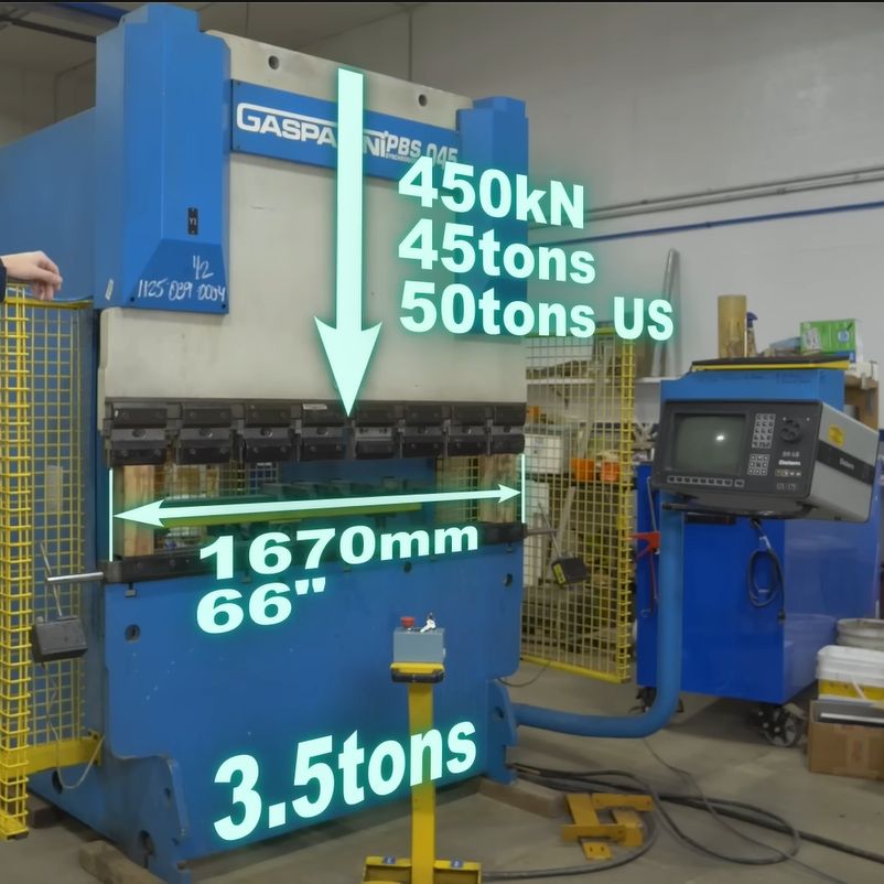
Press brakes are invaluable tools when working with sheet metal, but along with their almost infinite versatility comes a dizzying number of press brake types. After starting with an old-school, purely mechanical press brake, [Wes] of Watch Wes Work fame had been thinking of upgrading said press brake to a hydraulic configuration, but soured on this after facing all the disadvantages of the chosen approach. Thus, one does what any rational person does and purchases a used and very much untested 45-ton computer-controlled hydraulic press brake.
The video first explores the pros and cons of the various types of press brakes, with the issue of providing a balanced force across the entirety of the press brake’s dies being the largest problem. Although various mechanical and hydraulic solutions were attempted over the decades, a computer-controlled press brake like this Gasparini PBS 045 that [Wes] got is probably one of the more effective solutions, even if it provides the headache of more electrical and electronic things that can go wrong. The above screenshot of its basic workings should make that quite obvious, along with [Wes]’s detailed explanation.
As it turned out, this about 25-year-old Italian press brake wasn’t in such a terrible nick, but needed some badly needed TLC and obligatory breaker testing to bring it back to life. While it doesn’t like you not centering the part, this can be worked around by specifying that the part is actually larger than it is. Although [Wes] got it working well enough to do some work with it, it still has some gremlins left in it that will hopefully be hunted down over the coming time and video(s).
When it comes to designing a mopping robot, there are a number of approaches you can pick from, including just having the movement of the robot push the soggy mop over the floor, having spinning pads, or even a big spinning roller. But what difference does it make? Recently the [Vacuum Wars] channel ran a comparison to find out the answer.
The two spinning pad design is interesting, because it allows for the bot to move closer to objects or walls, and the base station doesn’t need the active scrubber that the simple static pad requires. The weakness of both types of flat mop design is that they are quickly saturated with dirt and moisture, after which they’ll happily smear it over the floor.
The spinning roller is the most complex, with the robot having its own onboard water tank, and a way to extract the dirty water from the mop and store it for disposal in the base station. Theoretically this would be the clear winner, with basically all of them having features like avoiding carpet.
Taking the test data from 150 different mopping robots that were made to clean up dried-up coffee stains, the results weren’t as clear-cut as one might perhaps expect due to the very limited scope of the test. But the comments to the video are perhaps more revealing. After all, most people don’t briefly run their robot mop over a few dried-up stains, but are faced with more severe real-life scenarios.
One commentator mentions their dogs dragging in a lot of mud on rainy days, in which case the spinning pads robot would end up spreading a thin film of mud across the floor. After upgrading to a spinning roller version this issue was resolved, though it’s readily admitted to be the more expensive system, with a much larger base station.
When in the video you see the details of what each approach involves on the side of the robot, the base station and the human caretaker, trade-offs are clear. Having the fixed flat pad is simple, but moves all complexity to the base station, with the spinning pads removing at least the need to motorize the base station. If you have small children or pets with muddy paws around, neither option works well, so you either have to whip out the human-powered mop or shell out for the high-end robotic solution.
 Before the refrigerator became a normal part of any kitchen, those with enough money to throw around could get an icebox, which used melting ice to cool food and drinks in a second compartment. As refrigerators became available for sale in the 1920s, this created somewhat awkward transition models, like the 1924 Frigidaire B-9 that [David Allen] recently got offered for a restoration. This was part of the restoration of a 1926 house, which foresaw putting this venerable unit back into operation.