An audio amplifier was once a fairly simple analogue device, but in recent decades a typical home entertainment amplifier will have expanded to include many digital functions. When these break they are often proprietary and not easy to repair, as was the case with a broken Pioneer surround-sound device given to [Boz]. It sat on the shelf for a few years until he had the idea of a jukebox for his ripped CDs, and his returning it to life with a new main board is something to behold.
Internally it’s a surprisingly modular design, meaning that the front panel with its VFD display and driver were intact and working, as were the class AB amplifier and its power supply. He had the service manual so reverse engineering was straightforward, thus out came the main board in favor of a replacement. He took the original connectors and a few other components, then designed a PCB to take them and a Raspberry Pi Pico and DAC. With appropriate MMBASIC firmware it looks as though it was originally made this way, a sense heightened by a look at the motherboard inside (ignoring a couple of bodges).
After initially announcing that Bose will completely turn off all ‘smart’ features in its SoundTouch series of speaker products, the company has seemingly responded to the wave of unhappy feedback with a compromise solution. Rather than the complete shutdown and cut-off that we reported on previously, Bose will now remove cloud support as its servers shut down, but the SoundTouch mobile app will get an update that gets truncated to just the local support functions. Bose also made the SoundTouch Web API documentation available as a PDF document.
The shutdown date has also been extended from the original February 18 to May 6th of this year. Although these changes mean that the mobile app can no longer use music services, features like grouping speakers and controlling playback will keep working. Features such as presets which were cloud-based will naturally stop working.
With the web API documentation made public it remains to be seen how helpful this will be. From a quick glance at the PDF documentation it appears to be a typical REST API, using HTTP on port 8090 on the SoundTouch device, with an SGML-style tag system to format messages. In so far as the community hasn’t already reverse-engineered this API it’s at least nice to have official documentation.
Many projects on these pages do clever things with video. Whether it’s digital or analogue, it’s certain our community can push a humble microcontroller to the limit of its capability. But sometimes the terminology is a little casually applied, and in particular with video there’s an obvious example. We say “PAL”, or “NTSC” to refer to any composite video signal, and perhaps it’s time to delve beyond that into the colour systems those letters convey.
Know Your Sub-carriers From Your Sync Pulses
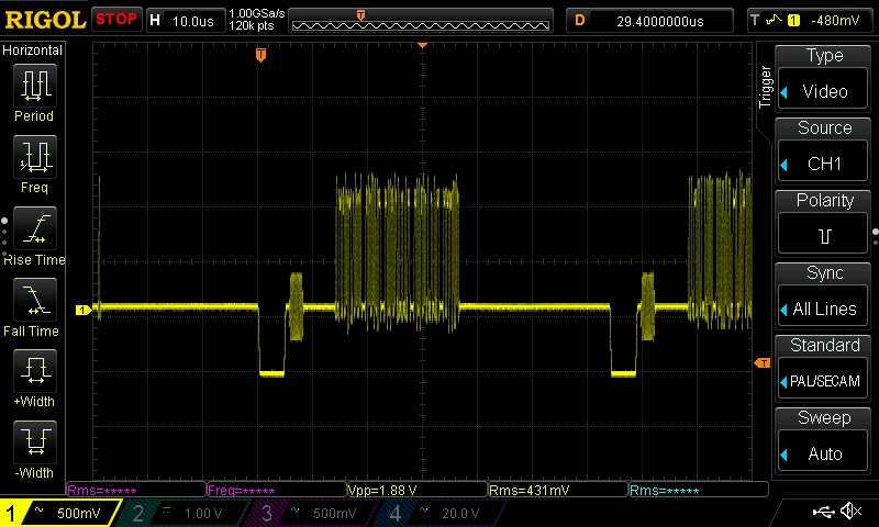
A close-up on a single line of composite video from a Raspberry Pi.
A video system of the type we’re used to is dot-sequential. It splits an image into pixels and transmits them sequentially, pixel by pixel and line by line. This is the same for an analogue video system as it is for many digital bitmap formats. In the case of a fully analogue TV system there is no individual pixel counting, instead the camera scans across each line in a continuous movement to generate an analogue waveform representing the intensity of light. If you add in a synchronisation pulse at the end of each line and another at the end of each frame you have a video signal.
But crucially it’s not a composite video signal, because it contains only luminance information. It’s a black-and-white image. The first broadcast TV systems as for example the British 405 line and American 525 line systems worked in exactly this way, with the addition of a separate carrier for their accompanying sound.
The story of the NTSC colour TV standard’s gestation in the late 1940s is well known, and the scale of their achievement remains impressive today. NTSC, and PAL after it, are both compatible standards, which means they transmit the colour information alongside that black-and-white video, such that it doesn’t interfere with the experience of a viewer watching on a black-and-white receiver. They do this by adding a sub-carrier modulated with the colour information, at a frequency high enough to minimise its visibility on-screen. for NTSC this is 3.578MHz, while for PAL it’s 4.433MHz. These frequencies are chosen to fall between harmonics of the line frequency. It’s this combined signal which can justifiably be called composite video, and in the past we’ve descended into some of the complexities of its waveform.
It’s Your SDR’s I and Q, But Sixty Years Earlier
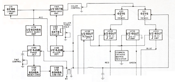
Block diagram of an NTSC colour decoder as found in a typical 1960s American TV set. Color TV Servicing, Buchsbaum, Walter H, 1968.
An analogue colour TV camera produces three video signals, one for each of the red, green, and blue components of the picture. Should you combine all three you arrive at that black-and-white video waveform, referred to as the luminance, or as Y. The colour information is then reduced to two further signals by computing the difference between the red and the luminance, or R-Y, and the blue and the luminance, or B-Y. These are then phase modulated as I-Q vectors onto the colour sub-carrier in the same way as happens in a software-defined radio.
At the receiver end, the decoder isolates the sub-carrier, I-Q demodulates it, and then rebuilds the R, G, and B, with a summing matrix. To successfully I-Q demodulate the sub-carrier it’s necessary to have a phase synchronised crystal oscillator, this synchronisation is achieved by sending out a short burst of the colour sub-carrier on its own at the start of the line. The decoder has a phase-locked-loop in order to perform the synchronisation.
So, Why The PAL Delay Line?
A PAL decoder module from a 1970s ITT TV. The blue component in the middle is the delay line. Mister rf, CC BY-SA 4.0.
There in a few paragraphs, is the essence of NTSC colour television. How is PAL different? In essence, PAL is NTSC, with some improvements to correct phase errors in the resulting picture. PAL stands for Phase Alternate Line, and means that the phase of those I and Q modulated signals swaps every line. The decoder is similar to an NTSC one and indeed an NTSC decoder set to that 4.433MHz sub-carrier could do a job of decoding it, but a fully-kitted out PAL decoder includes a one-line delay line to cancel out phase differences between adjacent lines. Nowadays the whole thing is done in the digital domain in an integrated circuit that probably also decodes other standards such as the French SECAM, but back in the day a PAL decoder was a foot-square analogue board covered in juicy parts highly prized by the teenage me. Since it was under a Telefunken patent there were manufacturers, in particular those from Japan, who would try to make decoders that didn’t infringe on that IP. Their usual approach was to create two NTSC decoders, one for each phase-swapped line.
So if you use “NTSC” to mean “525-line” and “PAL” to mean “625-line”, then everyone will understand what you mean. But make sure you’re including that colour sub-carrier, or you might be misleading someone.