When you’re driving a car with a stickshift, it’s pretty easy to keep track of which gear you’re in. That can be a little bit more difficult on something like a motorcycle with a sequential shifter. [decogabry] built a neat gearshift indicator to solve this issue.
An ESP32 devboard is used as the brain of the build. It’s paired with an ELM327 dongle over Bluetooth, which is able to hook into the bike’s ODB diagnostic port to pick up data like engine RPM, wheel speed, and coolant temperature. The first two factors are combined in order to calculate the current gear, since the ratio between engine RPM and wheel speed is determined directly by the gear selection. The ESP32 then commands a Philips ZM1020 Nixie tube to display the gear, driving it via a small nest of MPSA42 transistors. A separate self-contained power supply module is used to take the bike’s 12 volt supply up to the 170 volts needed to run the tube. There is also a small four-digit display used to show status information, RPM, and engine temperature.
Notably, [decogabry] made this build rather flexible, to suit any bike it might be installed upon. The gear ratios are not hard coded in software. Instead, there is a simple learning routine that runs the first time the system is powered up, which compares RPM and wheel speed during a steady-state ride and saves the ratios to flash.
We’ve featured projects before that used different techniques to achieve similar ends. It’s also interesting to speculate as to whether there’s a motorcycle vintage enough to suit a Nixie display while still having an ODB interface on board as standard. Meanwhile, if you’re cooking up your own neat automotive builds, don’t hesitate to drop us a line.
The electric vehicle revolution has created market forces to drive all sorts of innovations. Battery technology has progressed at a rapid pace, and engineers have developed ways to charge vehicles at ever more breakneck rates. Similarly, electric motors have become more powerful and more compact, delivering greater performance than ever before.
In the latter case, while modern EV motors are very capable things, they’re also reliant on materials that are increasingly hard to come by. Most specifically, it’s the rare earth materials that make their magnets so good. The vast majority of these minerals come from China, with trade woes and geopolitics making it difficult to get them at any sort of reasonable price. Thus has sprung up a new market force, pushing engineers to search for new ways to make their motors compact, efficient, and powerful.
Rare
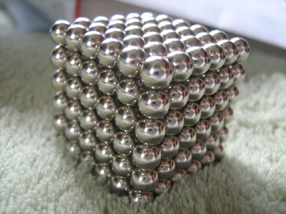
Many of us first came across neodymium magnets as a simple curiosity. Credit: XRDoDRX, CC BY-SA 3.0
Rare earth materials have become a hot button issue in recent decades, and they’ve also become a familiar part of our lives. If you remember playing with some curiously powerful magnets at some point, you’ve come across neodymium—a rare earth material of wide application. The element is alloyed with iron and boron to produce some of the strongest magnets readily available on the commercial market. You’ll find them in everything from hard drives to EV motors, and stuck to a great many fridges, where they’re quite hard to peel off. At times, neodymium is also alloyed with other rare earths, like terbium and dysprosium, which can help create powerful magnets that are able to resist higher temperatures without failure.
We come across these magnets all the time, so they might not feel particularly rare. Indeed, the rare earth elements—of which there are 17 in total—are actually fairly abundant in the Earth’s crust. The problem is that they are thinly spread, often only found as trace elements rather than in rich ore deposits that are economical to mine. Producing any useful amount of rare earth materials tends to require processing a great deal of raw material at significant cost. As it stands, China has gained somewhat of a monopoly on rare earths, controlling up to 92% of global processing capability and 60 to 70% of mining capacity. In happier times, this wouldn’t be such a problem. Sadly, with the extended battles being fought over global trade at the moment, it’s making access to rare earths both difficult and expensive.
This has become a particular problem for automotive manufacturers. It’s no good to design a wonderful motor that needs lots of fancy rare earth magnets, only to find out a year later that they’re no longer available and that production must shut down. Thus, there is a serious desire on the part of major automakers to produce high-performance motors that don’t require such fancy, hard-to-come-by materials. Even if they come with a small cost penalty in materials or manufacturing, they could save huge sums of money if they avoid a production shutdown at some point in the future. Large manufacturing operations are slow, lumbering things that need to run on long timescales to operate economically, and they can easily be derailed by supply disruptions. Securing a solid motor supply is thus key to companies looking to build EVs en masse in the immediate future.
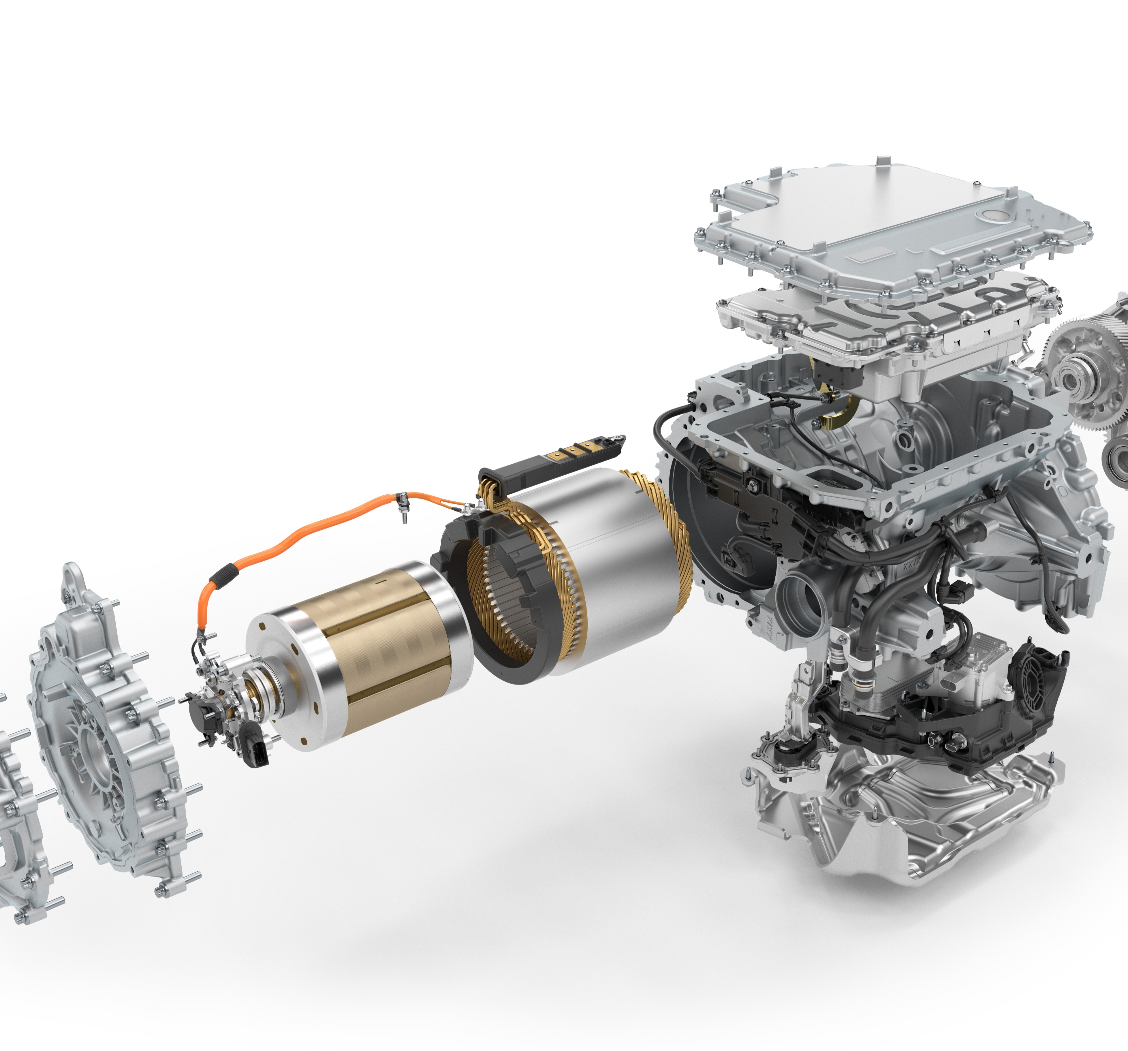
BMW’s new EV motors use electrically-excited coils in the rotor to generate the necessary magnetic field, instead of rare-earth magnets. Credit: BMW
BMW has, to a degree, solved the problem by making different kinds of motors. Rather than trying to find other ways to make powerful magnets, the German automaker put engineering efforts into developing highly-efficient motors that generate their own magnetic fields via electricity. Instead of using permanent magnets on the rotor, they use coils, which are electrically excited to generate a comparable magnetic field. Thus, rare earth magnets are replaced with coil windings, which are much easier to source. These motors are referred to as Electrically Excited Synchronous Motors (EESM), and are distinct from traditional induction motors as they are creating a magnetic field in the rotor via supplied electric current rather than via induction.
This method of construction does come with some trade offs, of course, such as heat generated by the rotor coils, and the need for slip rings or brushes to transfer power to the coils on the rotor. However, they manage to neatly sidestep the need for rare earth materials entirely. They are also more controllable. Since it’s possible to vary the magnetic field in the rotor as needed, this can be used to make efficiency gains in low-load situations. They’re also less susceptible to damage from overtemperature that could completely destroy the magnets in a permanent magnet motor.
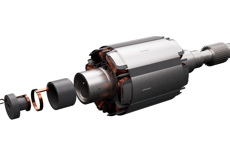
ZF is one of a number of motor manufacturers that has developed a range of EESM motors. Note the coils in the rotor where the permanent magnets would usually go. Credit: ZF
BMW was inspired to take this route because of a spike in neodymium prices well over a decade ago. Today, that decision is bearing fruit—with the company less fearful of supply chain issues and production line stoppages due to some pesky magnets. You’ll find EESM motors in a range of BMW products, from the iX1 to the i7, and even the compact CE 02 scooter. The company’s next generation of electric models will largely use EESM motors for rear-wheel-drive models, while using asynchronous motors up front to add all-wheel-drive to select models. The German automaker is not the only player in this space, either. A range of third-party motor manufacturers have gotten on board the EESM train, as well as other automakers like Nissan and Renault.
Nissan has similarly gotten onboard with EESM technology. Note the contact surfaces for the brushes used to deliver electricity to the coils in the motor.
Don’t expect every automaker to rush into this technology overnight. Retooling production lines to make different types of motors takes time, to say nothing of the supporting engineering required to control the motors and integrate them into vehicle designs. Many automakers will persevere with permanent magnet motors, doing what they can to secure rare earth supplies and shore up their supply chains. However, if the rare earth crisis drags on much longer, expect to see ever more reliance on new motor designs that don’t need rare earth magnets at all.
You’ve heard of wind tunnels– get some airflow going over a thingy, put some some smoke on, and voila! Flow visualization. How hard could it be? Well, as always, the devil is in the details and [toast] is down in there with him with this Hot-Wheels sized wind tunnel video.
To get good, laminar flow inside of a wind tunnel, there are important ratios to be followed– the inlet and outlet diameters must relate to the interior size to get the correct slope on the contraction and exhaust cones. You need a flow straightener on both ends. All of it can be easily 3D printed, as [toast] shows, but you have to know those design rules and pay attention to, which [toast] does… this time. One of his “don’t do this” examples in this video is previous build of his where he did not follow all the rules, and the difference is clear.
Now, unless you’re hooked on flow visualizations —guilty— or are a Hot-Wheels aficionado, since that’s what this wind tunnel is sized for, you probably won’t rush to gumroad to buy [toast]’s STLs. On the other hand, if you pay attention to the lessons [toast] has learned in this video you can apply them to wind tunnels of whatever size and construction technique you need, be it cardboard or junk box plastic and get a more stable result.
At some point during our primary school careers, most of us probably constructed a simple compass, often by floating a magnetized needle on a cork in a cup of water. The water in such a configuration not only lets the needle spin without friction, but also dampens out (so to speak) the needle’s tendency to swing back and forth across the north-south line. Liquid-filled compasses use the same principle, but even well-made compasses can develop bubbles when exposed to temperature or pressure variations. Rather than accept this unsightly state of affairs, [The Map Reading Company] designed a new kind of liquid-free, inductively-damped compass.
It’s hard to design a compass that settles quickly, even if it uses a strong magnet, because the Earth’s own magnetic field is just so weak, and the stronger the internal magnet is, the more likely it is to be thrown off by nearby magnetic objects. As a result, they tend to swing, overshoot, and oscillate around their final orientation for some time. Most compasses use liquid to damp this, but a few, mostly military compasses, use a conductive baseplate instead: as the magnet moves, it induces eddy currents in the baseplate, which create a weak magnetic field opposing its motion, slowing the magnet down. Inductively-damped compasses don’t get bubbles, but they don’t let you see a map through the baseplate. [The Map Reading Company] dealt with this by making the baseplate transparent and surrounding the compass needle with a ring of high-conductivity copper alloy. This gave him a clear baseplate compass for easy map reading which would never develop bubbles. It’s a simple hack, and should be easy to replicate, but it still seems to be a new design. In fact, [The Map Reading Company] is releasing most of the design to the public domain. Anyone can build this design.
If this prompts your interest in compasses, check out the Earth inductor compass. We’ve also seen a visualization of the eddy currents that damp these oscillations, and even seen them used to drive a bike.
If you live in snow country and own a home, you either have a snowblower or wish you did. The alternatives are either an expensive and potentially unreliable plow service, or back-breaking (and heart-attack inducing) shoveling. [RCLifeOn] was one of those people in the second category, until he decided to do something about it: electrifying a scrap snowblower with a blown engine.
The usual brushless DC motors and electronic speed controllers [RCLifeOn] has on hand to get his R/C life on with don’t quite have enough oomph to handle both functions of a snowblower. For those of you cursed to live in warmer climes, the modern snowblower is both self-propelled via its twin wheels, and generally has a two-stage powered snow-removal “blower” consisting of an auger to break up the snow and an impeller to blast it out of the machine and many meters off the driveway. On the traditional gas-powered models, these are both powered via belts off the same motor, but that wasn’t going to work.
He kept the belts, and simply used a pair of motors, each with their own ESCs that are controlled via oversized thumb wheels on the handles. The belts couple to the motors with 3D printed pulleys. Belt tension is achieved in the case of the wheels through a simple and sensible shimming arrangement. In the case of the blower motor, he uses a 3D printed adjustable mount to get the appropriate tension. To help it hold long-term (given the issues with creep in 3D prints) he’s got a bearing on a second mount opposite the motor. It holds up for his demo, which consists of clearing a driveway of 10cm of snow and then plowing through a pile larger than the mouth of the machine. In other words: it works.
The build, as unfortunately common on YouTube, is shy on specific details– but in this case that’s fine. Even if he’d open-sourced everything and posted STEP or STL files, it wouldn’t save much time since you’d pretty well have to re-engineer the build to fit your own snowblower, if you were so inclined. As with many hacks of this nature, the point of sharing it is to show how easy it is and provide the inspiration. As the cartoons used to say, “knowing is half the battle.”
If one was to re-implement this hack, we could not encourage you strongly enough to put in the standard dead-man’s switch, a feature commercial snowblowers share with things like lawnmowers. As annoying as it is to hang onto with frozen fingers, that safety feature is there for a reason.