Nothing lasts forever, and that includes the ROMs required to make a retrocomputer run. Even worse, what if you’re rolling your own firmware? Period-appropriate EPROMs and their programmers aren’t always cheap or easy to get a hold of these days. [Kyo-ta04] had that problem, and thanks to them, we now all have a solution: Pico2ROMEmu, a ROM emulator based on, you guessed it, the Raspberry Pi Pico2.
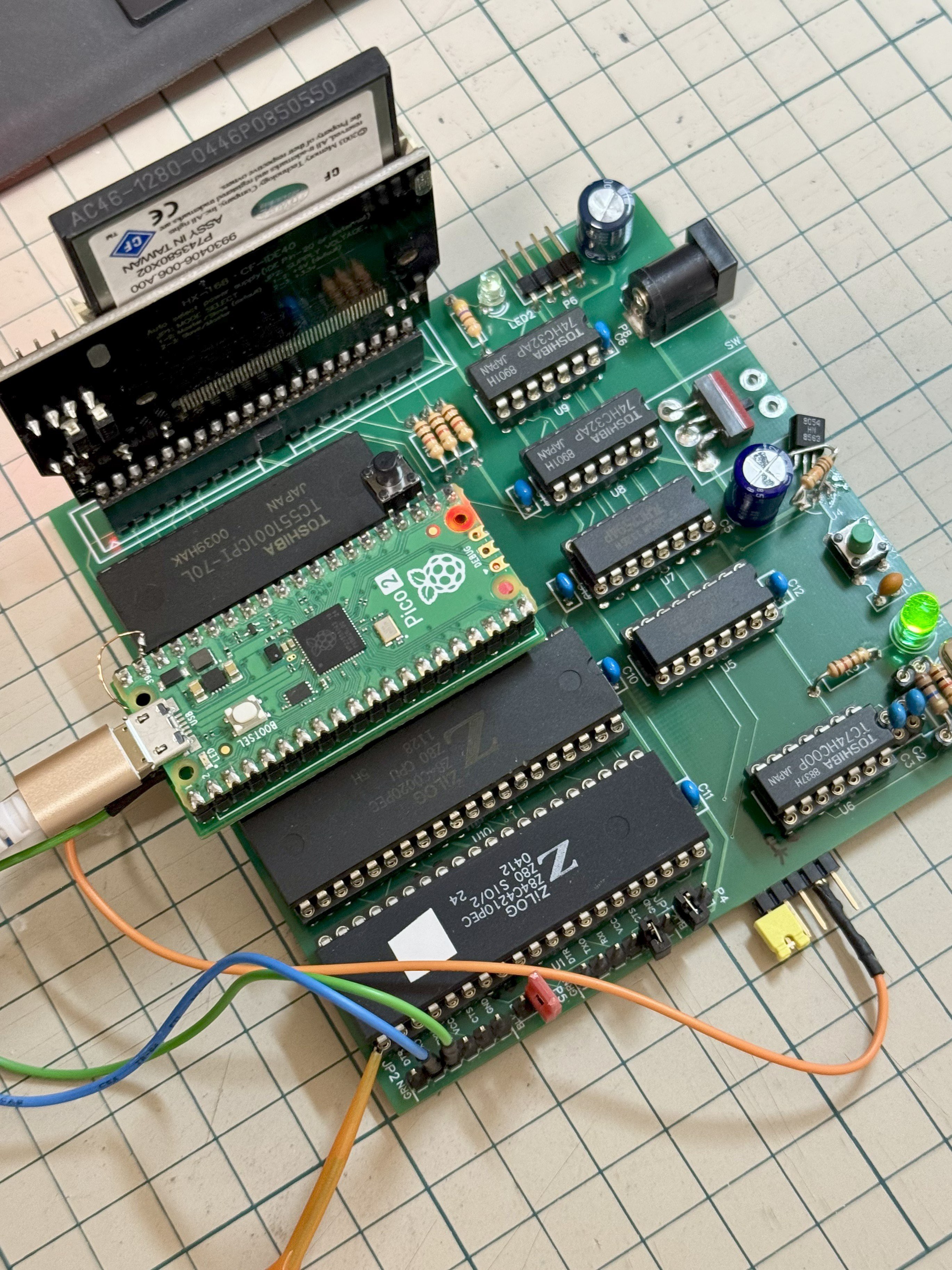
The Pico2ROMEmu in its natural habitat on a Z80 SBC.
The ROM emulator has been tested at 10MHz with a Z80 processor and 12MHz with an MC68000. An interesting detail here is that rather than use the RP2350’s RISC-V or ARM cores, [kyo-ta04] is doing all the work using the chip’s powerful PIO. PIO means “programmable I/O,” and if you need a primer, check this out. Using PIO means the main core of the microcontroller needn’t be involved — and in this context, a faster ROM emulator.
We’ve seen ROM emulators before, of course — the OneROM comes to mind, which can also use the RP2350 and its PIOs. That project hasn’t been chasing these sorts of speeds as it is focused on older, slower machines. That may change in the newest revision. It’s great to see another contender in this space, though, especially one to serve slightly higher-performance retrocomputers. Code and Gerbers for the Pico2RomeEMU are available on GitHub under an MIT license.
The Amiga was a great game system in its day, but there were some titles it was just never going to get. Sonic the Hedgehog was one of them– SEGA would never in a million years been willing to port its flagship platformer to another system. Well, SEGA might not in a million years, but [reassembler] has started that process after only thirty four.
Both the SEGA Mega Drive (that’s the Genesis for North Americans) and Amiga have Motorola 68k processors, but that doesn’t mean you can run code from one on the other: the memory maps don’t match, and the way graphics are handled is completely different. The SEGA console uses so-called “chunky” graphics, which is how we do it today. Amiga, on the other hand, is all about the bitplanes; that’s why it didn’t get a DOOM port back in the day, which may-or-may not be what killed the platform.
In this first video of what promises to be a series, [reassembler] takes us through his process of migrating code from the Mega Drive to Amiga, starting specifically with the SEGA loading screen animation, with a preview of the rest of the work to come. While watching someone wrestle with 68k assembler is always interesting, the automation he’s building up to do it with python is the real star here. Once this port is done, that toolkit should really grease the wheels of bringing other Mega Drive titles over.
It should be noted that since the Mega Drive was a 64 colour machine, [reassembler] is targeting the A1200 for his Sonic port, at least to start. He plans to reprocess the graphics for a smaller-palette A500 version once that’s done. That’s good, because it would be a bit odd to have a DOOM-clone for the A500 while being told a platformer like Sonic is too much to ask. If anyone can be trusted to pull this project off, it’s [reassembler], whose OutRun: Amiga Edition is legendary in the retro world, even if we seem to have missed covering it.
The past few months, we’ve been giving you a quick rundown of the various ways ores form underground; now the time has come to bring that surface-level understanding to surface-level processes.
Strictly speaking, we’ve already seen one: sulfide melt deposits are associated with flood basalts and meteorite impacts, which absolutely are happening on-surface. They’re totally an igneous process, though, and so were presented in the article on magmatic ore processes.
For the most part, you can think of the various hydrothermal ore formation processes as being metamorphic in nature. That is, the fluids are causing alteration to existing rock formations; this is especially true of skarns.
There’s a third leg to that rock tripod, though: igneous, metamorphic, and sedimentary. Are there sedimentary rocks that happen to be ores? You betcha! In fact, one sedimentary process holds the most valuable ores on Earth– and as usual, it’s not likely to be restricted to this planet alone.
Placer? I hardly know ‘er!
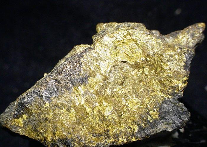
We’re talking about placer deposits, which means we’re talking about gold. In dollar value, gold’s great expense means that these deposits are amongst the most valuable on Earth– and nearly half of the world’s gold has come out of just one of them. Gold isn’t the only mineral that can be concentrated in placer deposits, to be clear; it’s just the one everyone cares about these days, because, well, have you seen the spot price lately?
Since we’re talking about sediments, as you might guess, this is a secondary process: the gold has to already be emplaced by one of the hydrothermal ore processes. Then the usual erosion happens: wind and water breaks down the rock, and gold gets swept downhill along with all the other little bits of rock on their way to becoming sediments. Gold, however, is much denser than silicate rocks. That’s the key here: any denser material is naturally going to be sorted out in a flow of grains. To be specific, empirical data shows that anything denser than 2.87 g/cm3 can be concentrated in a placer deposit. That would qualify a lot of the sulfide minerals the hydrothermal processes like to throw up, but unfortunately sulfides tend to be both too soft and too chemically unstable to hold up to the weathering to form placer deposits, at least on Earth since cyanobacteria polluted the atmosphere with O2.
Dry? Check. Windswept? Check. Aeolian placer deposits? Maybe! Image: “MSL Sunset Dunes Mosaic“, NASA/JPL and Olivier de Goursac
One form of erosion is from wind, which tends to be important in dry regions – particularly the deserts of Australia and the Western USA. Wind erosion can also create placer deposits, which get called “aeolian placers”. The mechanism is fairly straightforward: lighter grains of sand are going to blow further, concentrating the heavy stuff on one side of a dune or closer to the original source rock. Given the annual global dust storms, aeolian placers may come up quite often on Mars, but the thin atmosphere might make this process less likely than you’d think.
We’ve also seen rockslides on Mars, and material moving in this matter is subject to the same physics. In a flow of grains, you’re going to have buoyancy and the heavy stuff is going to fall to the bottom and stop sooner. If the lighter material is further carried away by wind or water, we call the resulting pile of useful, heavy rock an effluvial placer deposit.
Still, on this planet at least it’s usually water doing the moving of sediments, and it’s water that’s doing the sortition. Heavy grains fall out of suspension in water more easily. This tends to happen wherever flow is disrupted: at the base of a waterfall, at a river bend, or where a river empties into a lake or the ocean. Any old Klondike or California prospector would know that that’s where you’re going to go panning for gold, but you probably wouldn’t catch a 49er calling it an “Alluvial placer deposit”. Panning itself is using the exact same physics– that’s why it, along with the fancy modern sluices people use with powered pumps, are called “placer mining”. Mars’s dry river beds may be replete with alluvial placers; so might the deltas on Titan, though on a world where water is part of the bedrock, the cryo-mineralogy would be very unfamiliar to Earthly geologists.
Back here on earth, wave action, with the repeated reversal of flow, is great at sorting grains. There aren’t any gold deposits on beaches these days because wherever they’ve been found, they were mined out very quickly. But there are many beaches where black magnetite sand has been concentrated due to its higher density to quartz. If your beach does not have magnetite, look at the grain size: even quartz grains can often get sorted by size on wavy beaches. Apparently this idea came after scientists lost their fascination with latin, as this type of deposit is referred to simply as a “beach placer” rather than a “littoral placer”.
Kondike, eat your heart out: Fifty thousand tonnes of this stuff has come out of the mines of Witwatersrand.
While we in North America might think of the Klondike or California gold rushes– both of which were sparked by placer deposits– the largest gold field in the world was actually in South Africa: the Witwatersrand Basin. Said basin is actually an ancient lake bed, Archean in origin– about three billion years old. For 260 million years or thereabouts, sediments accumulated in this lake, slowly filling it up. Those sediments were being washed out from nearby mountains that housed orogenic gold deposits. The lake bed has served to concentrate that ancient gold even further, and it’s produced a substantial fraction of the gold metal ever extracted– depending on the source, you’ll see numbers from as high as 50% to as low as 22%. Either way, that’s a lot of gold.
Witwatersrand is a bit of an anomaly; most placer deposits are much smaller than that. Indeed, that’s in part why you’ll find placer deposits only mined for truly valuable minerals like gold and gems, particularly diamonds. Sure, the process can concentrate magnetite, but it’s not usually worth the effort of stripping a beach for iron-rich sand.
The most common non-precious exception is uraninite, UO2, a uranium ore found in Archean-age placer deposits. As you might imagine, the high proportion of heavy uranium makes it a dense enough mineral to form placer deposits. I must specify Archean-age, however, because an oxygen atmosphere tends to further oxidize the uraninite into more water-soluble forms, and it gets washed to sea instead of forming deposits. On Earth, it seems there are no uraninite placers dated to after the Great Oxygenation; you wouldn’t have that problem on Mars, and the dry river beds of the red planet may well have pitchblende reserves enough for a Martian rendition of “Uranium Fever”.
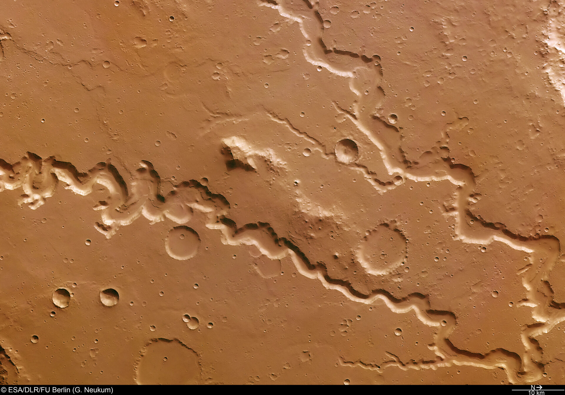
If you were the Martian, would you rather find uranium or gold in those river bends? Image: Nandes Valles valley system, ESA/DLR/FU Berlin
While uranium is produced at Witwatersrand as a byproduct of the gold mines, uranium ore can be deposited exclusively of gold. You can see that with the alluvial deposits in Canada, around Elliot Lake in Ontario, which produced millions of pounds of the uranium without a single fleck of gold, thanks to a bend in a three-billion-year-old riverbed. From a dollar-value perspective, a gold mine might be worth more, but the uranium probably did more for civilization.
Lateritization, or Why Martians Can’t Have Pop Cans
Speaking of useful for civilization, there’s another type of process acting on the surface to give us ores of less noble metals than gold. It is not mechanical, but chemical, and given that it requires hot, humid conditions with lots of water, it’s almost certainly restricted to Sol 3. As the subtitle gives it away, this process is called “lateritization” and is responsible for the only economical aluminum deposits out there, along with a significant amount of the world’s nickel reserves.
The process is fairly simple: in the hot tropics, ample rainfall will slowly leech any mobile ions out of clay soils. Ions like sodium and potassium are first to go, followed by calcium and magnesium but if the material is left on the surface long enough, and the climate stays hot and wet, chemical weathering will eventually strip away even the silica. The resulting “Laterite” rock (or clay) is rich in iron, aluminum, and sometimes nickel and/or copper. Nickel laterites are particularly prevalent in New Caledonia, where they form the basis of that island’s mining industry. Aluminum-rich laterites are called bauxite, and are the source of all Earth’s aluminum, found worldwide. More ancient laterites are likely to be found in solid form, compressed over time into sedimentary rock, but recent deposits may still have the consistency of dirt. For obvious reasons, those recent deposits tend to be preferred as cheaper to mine.
That red dirt is actually aluminum ore, from a 1980s-era operation on the island of Jamaica. Image from “Bauxite” by Paul Morris, CC BY-SA 2.0
When we talk about a “warm and wet” period in Martian history, we’re talking about the existence of liquid water on the surface of the planet– we are notably not talking about tropical conditions. Mars was likely never the kind of place you’d see lateritization, so it’s highly unlikely we will ever find bauxite on the surface of Mars. Thus future Martians will have to make due without Aluminum pop cans. Of course, iron is available in abundance there and weighs about the same as the equivalent volume of aluminum does here on Earth, so they’ll probably do just fine without it.
Most nickel has historically come from sulfide melt deposits rather than lateralization, even on Earth, so the Martians should be able to make their steel stainless. Given the ambitions some have for a certain stainless-steel rocket, that’s perhaps comforting to hear.
It’s important to emphasize, as this series comes to a close, that I’m only providing a very surface-level understanding of these surface level processes– and, indeed, of all the ore formation processes we’ve discussed in these posts. Entire monographs could be, and indeed have been written about each one. That shouldn’t be surprising, considering the depths of knowledge modern science generates. You could do an entire doctorate studying just one aspect of one of the processes we’ve talked about in this series; people have in the past, and will continue to do so for the foreseeable future. So if you’ve found these articles interesting, and are sad to see the series end– don’t worry! There’s a lot left to learn; you just have to go after it yourself.
Plus, I’m not going anywhere. At some point there are going to be more rock-related words published on this site. If you haven’t seen it before, check out Hackaday’s long-running Mining and Refining series. It’s not focused on the ores– more on what we humans do with them–but if you’ve read this far, it’s likely to appeal to you as well.
Back during WWII, Chrysler bodged five inline-6 engines together to create the powerful A57 multibank tank engine. [Maisteer] has some high-revving inline-4 motorcycle engines he’s trying to put together too, but unlike 1940s Chrysler, he also has a trombone… and a lot more RPMs to deal with.
The Chrysler flatheads were revving at a few thousand RPM– their redline was almost certainly in the three-thousand range. [Maisteer] is working at 15,000 RPM, which is where the real challenge of this build lies: the trombone in the image is just for fun. He wanted to use a heavy chain to link the crankshafts, but at that rotational speed, a heavy chain becomes really heavy— or at least, it feels a force many times its weight due to centrifugal force. The lietmotief of this video is a quote by an automotive engineer to the effect that chains don’t work over 10,000 RPM.
That leads to a few problems for the intrepid “not an engineer” that take most of the video to deal with and ultimately doom the engine linkage– for now. Not before he gets an iconic 8-cylinder sound out (plus some fire) out of a trombone, though. Of particular note is the maker-type workflow Hackaday readers will appreciate: he 3D scans the engines, CADs up parts he needs and sends away to have them CNC’d and SLS printed.
Hacking motorcycle engines into cars is nothing new. Hacking them together into franken-engines is something we see less often.
Thanks to [Keith Olson] for the tip! Remember, if you want to toot your own horn– or toot about someone else’s project, for that matter–the tips line is always open.
One easy way to make a very accurate clock is with a WiFi-enabled microcontroller like an ESP32 and a display: set up NTP, and you’ll never be off by more than a minute. This water clock project by [Liebregts] is not like that — there are no electronics to speak of, and if the clock is ever in sync to within a single minute, well, we’d be surprised.
We’re impressed to see it working regardless. Sure, it’s not exactly high-tech; the floating siphon mechanism [Liebregts] is using to get a steady flow out of the main reservoir dates back to 250 BC. On the other hand, since this style of time keeper has been out of fashion since the fall of Rome, [Liebregts] couldn’t just grab something off GitHub or ask ChatGPT to design it for them. This is real human engineering. The reservoir is even scaled to the four-hour timing of [Liebregts] workday — it gets refilled at lunch along with its maker.
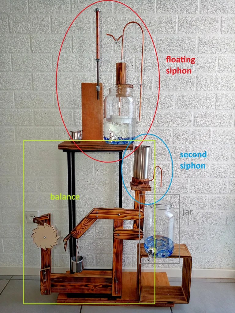
The water clock in all its glory, plus diagrammatic labels.
In a clever build detail, the floating siphon tube also holds a pointer to an hour indicator. For minutes, his mechanism seems unique, though it’s related to another ancient trick, the Pythagorean cup. Pythagoras’s devious cup had a hidden siphon that spilled its contents if you filled it beyond a set level, and so does the secondary reservoir of [Liebregts] water clock.
Since the secondary reservoir is linked to a counterweight with a pivot, it goes up and down over the course of approximately 5 minutes — but rather than linking that to another linear indicator, [Liebregts] is using that mechanism to advance a saw-toothed gear that is marked with 5-12 in analog-clock fashion for a touch of modernity. See it in action in the demo video below.
That last part might confuse a time traveler from Ancient Rome or Greece, but they’d instantly recognize this creation as a clock, which many modern observers might not. Still, once they learn to read it you can be sure that [Liebergts]’s friends will never be late to a gladiator fight again — and not just because Constantine banned them in 325 AD. Apparently nobody listened to that ban anyway.
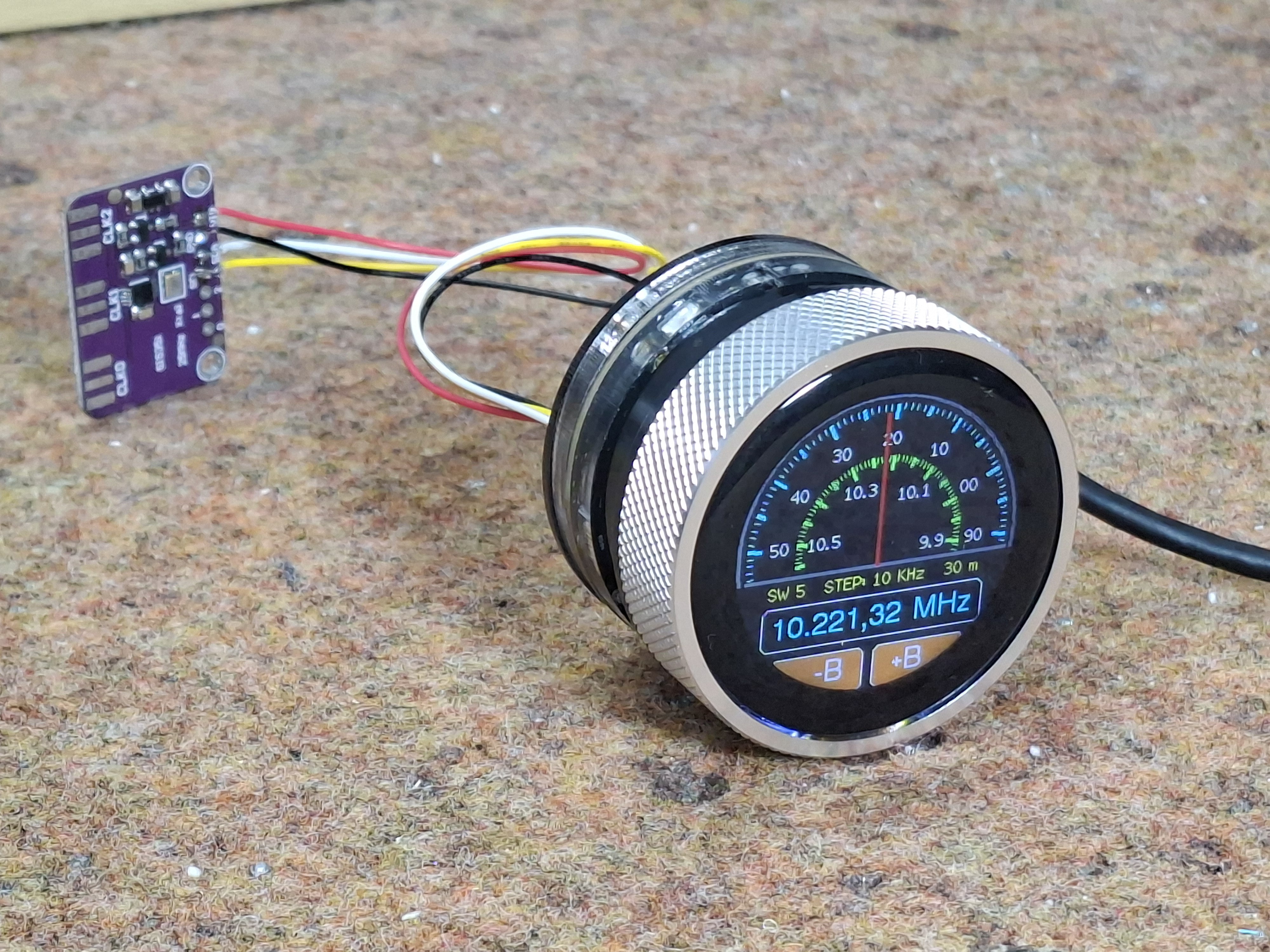
Not every project has to be complicated– reinventing the wheel has its place, but sometimes you find a module or two that does exactly what you want, and the project is more than halfway done. That the kind of project [mircemk]’s Simple Retro Style VFO is — it’s a variable frequency oscillator for HAM and other use, built with just a couple of modules.
Strictly speaking, this is all you need for the project.
The modules in question are the SI5351 Clock Generator module, which is a handy bit of kit with its own crystal reference and PLL to generate frequencies up to 150 MHz, and the Elecrow CrowPanel 1.28inch-HMI ESP32 Rotary Display. The ESP32 in the CrowPanel controls the SI5351 module via I2C; control is via the rest of the CrowPanel module. This Rotary Display is a circular touchscreen surrounded by a rotary display, so [mircmk] has all the inputs he needs to control the VFO.
To round out the parts count, he adds an appropriate connector, plus a power switch, red LED and a lithium battery. One could include a battery charger module as well, but [mircmk] didn’t have one on hand. Even if he had, that still keeps the parts count well inside the single digits. If you like video, we’ve embedded his about the project below; if not the write up on Hackaday.io is upto [mircmk]’s typical standard.
People have been using the SI5351 to make VFOs for years now, but the addition of the round display makes for a delightfully retro presentation.
It’s clock time again on Hackaday, this time with a lovely laser-cut biretrograde clock by [PaulH175] over on Instructables. If you’ve never heard of a ‘biretrograde clock,’ well, we hadn’t either. This is clearly a form of retrograde clock, which unlike the name implies doesn’t spin backwards but oscillates in its motion– the hands ‘go retrograde’ the same way the planets do.
The oscillating movement is achieved via a pair of cams mounted on the hour and minute shafts of a common clock mechanism. As the shafts (and thus cams) turn, the minute and hour arms are raised and drop. While that could itself be enough to tell the time, [Paul] goes one further and has the actual hands on pivots driven by a gear mechanism on the cam-controlled arms. You might think that that extra reversal is what makes this a ‘biretrograde clock’ but in the clockmaker’s world that’s just saying it’s a retrograde clock with two indicators: in this case, minute and hour.
It’s a fairly rare way to make a clock, but we’ve seen one before. That older project was 3D printed, which might be more your speed; if you prefer laser-cutting, though, [Paul]’s Instructable includes SVG files. Alternatively, you could take a different approach and use voltmeters to get the same effect.
In Dune, the Fremen people of Arrakis practice an odd future hybrid religion called “zensunni.” This adds an extra layer of meaning to the title of [Mark Rehorst]’s Arrakis 3.0 sand table, given that the inspiration for the robotic sand table seems to be Zen gardens from Japan.
The dunes on the tabletop version of Arrakis owe nothing to sand worms, but are instead created a rolling metal ball. With all workings happening below, it looks quite magical to the uninitiated, but of course it’s not magic: it’s magnets. Just beneath the tabletop and its sands, the steel ball is being dragged along by the magnetic field of a powerful neodynium magnet.
That magnet is mounted in a CoreXY motion system that owes more than a little bit to modern 3D printers. Aside from the geometry, it’s using the standard G6 belt we see so often, along with a Duet3D mainboard, NEMA 17 steppers, and many 3D printed parts to hold its aluminum extrusions together. Thanks to that printer-inspired motion system, the ball can whirl around at 2000 mm/s, though [Mark] prefers to run slower: the demo video below shows operation at 1000 mm/s before the sand has been added.
This build was designed for ease of construction and movement: sized at 2’x4′ (about 61 cm x 122 cm), it fits through doors and fits an off-the-shelf slab of coffee table glass, something that [Mark] wishes he’d considered when building version two. That’s the nice thing about jumping in on a project someone’s been iterating for a while: you’ve got the benefit of learning from their mistakes. You can see the roots of this design, and what has changed, from the one he showed us in 2020.
Naturally you’re not limited to CoreXY for a sand table, though it is increasingly popular — we’ve seen examples with polar mechanisms and even a SCARA arm.
You know those old cliche that the younger generations have begun to cynically despise: “follow your dreams!” “You can be anything you put your mind to!” — well, perhaps they are true on occasion. For instance when [rctestflight] had PCBs that dreamed of becoming a hydrofoil, he found a way to make that dream come true.
It’s kind of obvious in retrospect: printed circuit boards are made of FR4, which is a form of fiberglass, and you know what else is commonly made of fiberglass? Boats. So yes, the material is suited for this task. The fact that solder joints hold up to use in a little remote-control hydrofoil is less obvious, but good to know. It certainly makes for easier assembly for those of us who have developed an allergy to epoxy.
Ease of assembly wasn’t really the point here: the point was that by making the “mast” of the hydrofoil out of PCB– that’s the part that holds the underwater wing– [rctestflight] figured he could (shock!) print a circuit onto it. Specifically, a liquid-level sensor, and because microcontrollers are so cheap these days he went the “total overkill” route of embedding an ESP32 on each mast. He started with a resistive sensor, but since those self-corrode too quickly, the team switched to a capacitive sensor that doesn’t need to form a galvanic cell in salt water. Come to think of it, that might still be a problem with the solder joint between the PCBs. Good thing nobody will be riding this one.
Having such a sensor and brain close-coupled allows for a faster control loop than the sonar [rctestflight] had previously been using to control his hydrofoil’s altitude.. Pivoting each mast with its own servo made for a smooth flight over the water— well, once they got the PID tuning set, anyway. Check it out in the video embedded below.
There’s just something about an analog synthesizer. You’d think that for electronic music, digital sampling would have totally taken over by now, but that’s really not true. The world of analog synths is alive and well, and [Polykit] has a new, open-source polyphonic synthesizer to add to the ever-growing chorus of electronic instruments.
The analog part is thanks to the eight identical voice cards that plug into the machine’s mainboard: each one has a voltage controlled oscillator to generate tones, an envelope generator, multiple voltage-controlled amplifiers, and even a pole mixing filter which is also, yes, voltage controlled. Each voice card outputs stereo, and yes, there are controllable mixing circuits for left and right output.
All that voltage control means a lot of lines from digital-to-analog converters (DACs), because while this is an analog synth, it does have a MIDI interface, and that means that a microcontroller needs to be able to speak voltage. In this case, the brains are an ATmega2560. Instead of stacking the board with enough expensive DACs to interpret the MCU’s digital signals, [Polykit] is instead is using some clever tricks to get more work out of the one DAC he has. Some things get tied together on all eight voices, like the envelope parameters; other values are run through a demultiplexer to make the most possible use of the analog lines available. Of course that necessitates some latching circuitry to hold the demuxed values on those lines, but it’s still cheaper than multiple high-quality DACs.
It’s a well-thought out bit of kit, down to the control panel and acrylic case, and the writeup is worth reading to get the full picture. The voice cards, main board and control board all have their own GitHub repositories you can find at the bottom of the main page. If you’re into video, [Polykit] has a whole series on this project you might want to check out on Makertube; we’ve embedded the first one below.
If you want to get your toes wet in the wonderful world of synthesizers, this library of seventy synths is an amazing place to start, because it has great simple projects.
Transcutaneous Electrical Nerve Stimulation (TENS) is one of those things that sounds like it must be woo when you first hear of it. “A trickle of current that can deal with chronic pain better than the pills we’ve been using for decades? Yeah, and what chakras do you hook this doo-hickie up to?” It seems too good to be true, but in fact it’s a well-supported therapy that has become part of scientific medicine. There are no crystals needed, and you’re applying electrodes to the effected area, not your chakras. Like all medical devices, it can be expensive if you have to buy the machine out-of-pocket… but it is just a trickle of current. [Leon Hillmann] shows us its well within the range of hackability, so why not DIY?
[Leon]’s TENS machine is specifically designed to help a relative with hand problems, so breaks out electrodes for each finger, with one on the palm serving as a common ground. This type of TENS is “monophasic”– that is, DC, which is easier than balancing current flowing in two directions through quivering flesh. The direct current is provided at 32 V to the digit electrodes, safely kept to a constant amperage with a transistor-based current limiting circuit. The common ground in the palm is pulsed at a rate set by an ATmega32U4 and thus controllable: 14 Hz is given as an example.
Obviously if you want to reproduce this work you’re doing it at your own risk and need to consult with relevant medical professionals (blah blah blah, caveat gluteus maximus) but this particular sort of medical device is a good fit for the average hacker. Aside from prosthetics, we haven’t seen that much serious medical hacking since the pandemic. Still, like with synthesizing medical drugs, this is the kind of thing you probably don’t want to vibe code.
For those of you who haven’t spent time in North America around this time of year, you may be unaware of two things: one, the obligatory non-stop loop of “All I Want For Christmas Is You” retail workers are subjected to starting November first, and two: there is a strong cultural association between Christmastime and model railroading that may not exist elsewhere. That may down to childhood memories of when we got our first trainsets, or an excellent postwar marketing campaign by Lionel. Either way, now that Mariah Carey is blaring, we’re thinking about our holiday track layouts. Which makes this long presentation on Wiring for Small Layouts by [Chicago Crossing Model Railroad] quite timely.
There are actually three videos in this little course; the first focuses mostly on the tools and hardware used for DCC wiring (that’s Digital Command Control), which will be of less interest to our readers– most of you are well aware how to perform a lineman’s splice, crimp connectors onto a wire, and use terminal blocks.
The second two videos are actually about wiring, in the sense of routing all the wires needed for a modern layout– which is a lot more than “plug the rheostat into the tracks in one spot” that our first Lionel boxed set needed. No, for the different accessories there are multiple busses at 5V, 12V and 24V along with DCC that need to be considered. Unsurprisingly enough given those voltages, he starts with an ATX power supply and breaks out from there.
Even if you’re not into model railroading, you might learn something from these videos if you haven’t done many projects with multiple busses and wire runs before. It’s far, far too easy to end up with a rats nest of wires, be they DCC, I2C or otherwise. A little planning can save some big headaches down the line, and if this is a new skill for you [Chicago Crossing Model Railroad] provides a good starting point for that planning. Just skip ahead a couple minutes for him to actually start talking if you don’t want the musical cliff notes montage at the start of the videos.
When people talk about the lack of a DOOM being the doom Commodore home computers, they aren’t talking about the C64, which was deep into obsolescence when demon-slaying suddenly became the minimal requirement for all computing devices. That didn’t stop [Kamil Wolnikowski] and [Piotr Kózka] from hacking together Greya ray-cast first-person shooter for the Commodore 64.
Grey bares more than a passing resemblance to id-software’s most-ported project. It apparently runs at 16 frames per second on a vanilla C64 — no super CPU required. The secret to the speedy game play is the engine’s clever use of the system’s color mapping functionality: updating color maps is faster than redrawing the screen. Yeah, that makes for rather “blockier” graphics than DOOM, but this is running on a Commodore 64, not a 386 with 4 MB of RAM. Allowances must be made. Come to think of it, we don’t recall DOOM running this smooth on the minimum required hardware — check out the demo video below and let us know what you think.
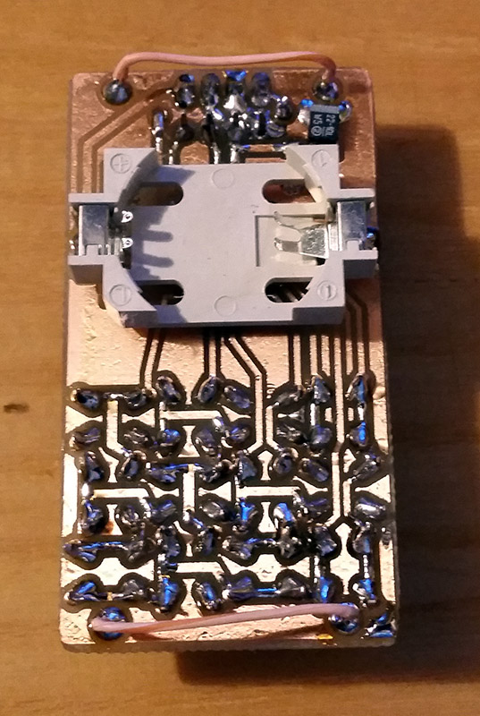
Once upon a time, owning a calculator watch was the epitome of cool. Well, for a very specific subset of the population with our own definition of “cool” anyway. The only thing cooler than wearing a calculator watch? Making a calculator watch, of course! If you do it as part of developing your own SDK for a popular RISC V microcontroller, all the better. That’s what [Miroslav Nemecek] did with his Antcalc watch, which is one of the demo projects for the CH32Lib SDK, which is currently under development at version 0.35 as this is written.
It appears as though the solid core wire on the back of the homemade PCB is used to hold the watch band, a nice little hack.
As you might guess, CH32LibSDK is targeting the super-cheap CH32 series of RISC V microcontrollers. Perhaps because the SDK is so early in development, there’s not much documentation outside of the example projects. The examples are all worth looking at, but our tipster wanted us to cover the Antcalc calculator watch specifically.
The Antcalc watch uses the SOP16-packaged CH32V002A4M6 to drive a small OLED display while taking input in Reverse Polish Notation from a dozen small buttons. We’re not sure how the cool kids feel about RPN these days, but that’s got to be worth extra nerd cred. Using a RISC V chip doesn’t hurt in that department, either.
For something so small– 30 mm x 55 mm–it’s looks like a decent little calculator, with 10 registers holding a mantissa of 21 digits and exponents up-to +/-99 in binary coded decimal. Seven layers on the dozen-key input pad mean most of the scientific functions you could ask for are available, along with the ability to record and replay upto 10 macros. There are also ten memory slots, all of which go into the chip’s onboard flash so are non-volatile during a battery swap. (Of which many will be necessary, since this appears to run on a single coin cell.)
There’s a tactile joy to the humble 3.5″ floppy that no USB stick will ever match. It’s not just the way they thunk into place in a well-made drive, the eject button, too, is a tactile experience not to be missed. If you were a child in disk-drive days, you may have popped a disk in-and-out repeatedly just for the fun of it — and if you weren’t a child, and did it anyway, we’re not going to judge. [igor] has come up with a physical game called “Floppy Flopper” that provides an excuse to do just that en masse, and it looks like lots of fun.
It consists of nine working floppy drives in a 3×3 grid, all mounted on a hefty welded-steel frame. Each drive has an RGB LED above it. The name of the game is to swap floppies as quickly as possible so that the color of the floppy in the drive matches the color flashing above it. Each successful insertion is worth thirteen points, tracked on a lovely matrix display. Each round is faster than the last, until you miss the window or mix up colors in haste. That might make more sense if you watch the demo video below.
[igor] could have easily faked this with NFC tags, as we’ve seen floppy-like interfaces do, or perhaps just use a color sensor. But no, those nine drives are all in working order. In the interest of speed — this is a timed challenge, after all, and we don’t need a PC slowing it down — each floppy is given its own microcontroller. Rather than reading data off the disk, only the disk’s write-protect and density holes are checked. He’s only using R, G, and B for floppy colors, so those four bits are enough. Unfortunately [igor]’s collection of floppies is very professional — lots of black and grey — so he needed to use colored stickers instead of technicolor plastic.
The project is open source, if you happen to have a stack of floppy drives of your own. If you don’t, but still want to play, the area, the Floppy Flopper is being exhibited at RADIONA in Rijeka, Croatia until December 5th 2025. If you happen to be in the neighborhood, it might be worth a trip.
If we had a nickle for every physical game that used a floppy drive, we’d have two nickles just this year. Which isn’t a lot, but it’s kind of neat to see so long after the last diskettes came off the production lines.
When the iconic “Boing Ball” first debuted 40 years ago, it was a wonder to behold. There was nothing like it in the home compuing world upto that time, and it showed that Commodore’s new “Amiga” was a powerhouse sure to last the test of time. Forty years later, the Amiga as we knew it then might not be with us anymore, but [Mark Wilson] is recreating its iconic demo on a microcontroller– but not just any microcontroller. “AMeagerBall” is an Arduino Uno exclusive, and it even tells the time.
Like the original “Boing Ball”, the demo is running at 320×240, though on a touch LCD shield instead of a CRT. Unlike some microcontrollers, the Uno doesn’t have the horsepower to just brute-force emulate a 1980s home computer, so [Mark] has had to recreate the boing ball from scratch. He’s not doing it with any graphics libraries, either. On the Uno that would be too slow, so [Mark] is driving the LCD directly to its appropriate registers, to stay close enough to the metal to make it work. That means if you’re going to try the code on his GitHub repository, you’ll need to be sure to use matching hardware or be prepared to port it.
One of the things about Amiga’s demo that was so impressive is that it hardly made use of the CPU, allowing the Workbench to be pulled up while the ball bounced. That’s not the case here, as the UNO doesn’t have any extra graphics chips. Still, [Mark] was able to squeeze enough horsepower out of everyone’s favourite ATmega to present us with an Amiga-styled clock– either analog, digital, or in the workbench title bar in that iconic blue-and-white. To keep the clock accurate, he’s squeezed an RTC module in, too. Lovely! The different clocks can be accessed via the touchscreen.
Oh, did we forget to mention that the touchscreen is implemented? This certainly stretches the hardware far enough to be considered a demo. If just a bouncing ball doesn’t work the UNO hard enough for you, try booting Linux.
Whenever there’s a superlative involved, you know that degree of optimization has to leave something else on the table. In the case of [PegorK]’s f32, the smallest ESP32 dev board we’ve seen, the cost of miniaturization is GPIO.
There’s only one GPIO pin broken out, and it’s pre-wired to an LED. That’s the bad news, and depending on what you want an ESP32 for, it might not phase you at all. What is impressive here, if not the number of I/O pins, is the size of the board: at 9.85 mm x 8.45 mm barely overhangs the USB-C socket that takes up one side of the board.
Pegor provides this helpful image in the readme so you know what you’re getting into with the 01005 resistors.
In order to get the ESP32-C3FH4 onto such a tiny board, all of the other support hardware had to be the smallest possible sizes– including resistors in 01005. If you don’t speak SMD, one could read that number code as “oh god too small” — at 0.4 mm x 0.2 mm it’s as minuscule as you’ll find– and [Pegor] hand soldered them.
OK, he did use a hot plate for the final step, but he did tin the pads manually with a soldering iron, which is still impressive. Most of us probably would have taken PCBWay up on their offer of assembly services, but not [Pegor]. Apparently part of the reason for this project was that he was looking for an excuse to use the really small footprint components.
Aside from leaving out GPIO and needing too-small SMD components, [Pegor] admits that pesky little details like antenna matching circuits and decoupling capacitors had to get cut to make the tiny footprint, so this board might be more of a stunt than anything practical. So what can you do with the smallest ESP32 board? Well, [Pegor] put up a basic web interface up to get you started blinking the built-in LED; after that, it’s up to you. Perhaps you might fancy a teeny-tiny minecraft server? If you can stand to increase the volume a little bit, we’ve seen how to hack a C3 for much better wifi performance.
Thanks to [Pegor] for the tip, and remember– submit your projects, big or small, we read ’em all!
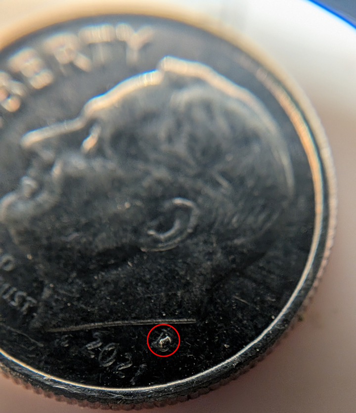
The increasing dominance of lithium cells in the market place leave our trusty NiMH cells in a rough spot. Sure, you can still get a chargers for the AAs in your life, but it’s old tech and not particularly stylish. That’s where [Maximilian Kern] comes in, whose SPINC project was recently featured in IEEE Spectrum— so you know it has to be good.
With the high-resolution LCD, the styling of this device reminds us a little bit of the Pi-Mac-Nano— and anything that makes you think of a classic Macintosh gets automatic style points. There’s something reminiscent of an ammunition clip in the way batteries are fed into the top and let out the bottom of the machine.
[Maximilian] thought of the, ah, less-detail-oriented amongst us with this one, as the dedicated charging IC he chose (why reinvent the wheel?) is connected to an H-bridge to allow the charger to be agnostic as to orientation. That’s a nice touch. An internal servo grabs each battery in turn to stick into the charging circuit, and deposits it into the bottom of the device once it is charged. The LCD screen lets you monitor the status of the battery as it charges, while doubling as a handy desk clock (that’s where the RP2040 comes in). It is, of course powered by a USB-C port as all things are these days, but [Maximilian] is just drawing from the 5V line instead of making proper use of USB-C Power Delivery. (An earlier draft of this article asserted incorrectly that the device used USB-C-PD.) Fast-charging upto 1A is enabled, but you might want to go slower to keep your cells lasting as long as possible. Firmware, gerbers and STLs are available on GitHub under a GPL-3.0 license– so if you’re still using NiCads or want to bring this design into the glorious lithium future, you can consider yourself welcome to.
We recently featured a AA rundown, and for now, it looks like NiMH is still the best bang for your buck, which means this project will remain relevant for a few years yet. Of course, we didn’t expect the IEEE to steer us wrong.
I’m sitting in front of an old Sayno Plasma TV as I write this on my media PC. It’s not a productivity machine, by any means, but the screen has the resolution to do it so I started this document to prove a point. That point? Plasma TVs are awesome.
Always the Bridesmaid, Never the Bride
An Egyptian god might see pixels on an 8K panel, but we puny mortals won’t. Image “Horus Eye 2” by [Jeff Dahl]The full-colour plasma screens that were used as TVs in the 2000s are an awkward technological cul-de-sac. Everyone knows and loves CRTs for the obvious benefits they offer– bright colours, low latency, and scanlines to properly blur pixel art. Modern OLEDs have more resolution than the Eye of Horus, never mind your puny human orbs, and barely sip power compared to their forbearers. Plasma, though? Not old enough to be retro-cool, not new enough to be high-tech, plasma displays are sadly forgotten.
It’s funny, because I firmly believe that without plasma displays, CRTs would have never gone away. Perhaps for that I should hate them, but it’s for the very reasons that Plasma won out over HD-CRTs in the market place that I love them.
What You Get When You Get a Plasma TV
I didn’t used to love Plasma TVs. Until a few years ago, I thought of them like you probably do: clunky, heavy, power-hungry, first-gen flatscreens that were properly consigned to the dustbin of history. Then I bought a house.
The house came with a free TV– a big plasma display in the basement. It was left there for two reasons: it was worthless on the open market and it weighed a tonne. I could take it off the wall by myself, but I could feel the ghost of OSHA past frowning at me when I did. Hauling it up the stairs? Yeah, I’d need a buddy for that… and it was 2020. By the time I was organizing the basement, we’d just gone into lockdown, and buddies were hard to come by. So I put it back on the wall, plugged in my laptop, and turned it on.
I was gobsmacked. It looked exactly like a CRT– a giant, totally flat CRT in glorious 1080p. When I stepped to the side, it struck me again: like a CRT, the viewing angle is “yes”.
How it Works
None of this should have come as a surprise, because I know how a Plasma TV works. I’d just forgotten how good they are. See, a Plasma TV really was an attempt to get all that CRT goodness in a flat screen, and the engineers at Fujitsu, and later elsewhere, really pulled it off.
Like CRTs, you’ve got phosphors excited to produce points of light to create an image– and only when excited, so the blacks are as black as they get. The phosphors are chemically different from those in CRTs but they come in similar colours, so colours on old games and cartoons look right in a way they don’t even on my MacBook’s retina display.
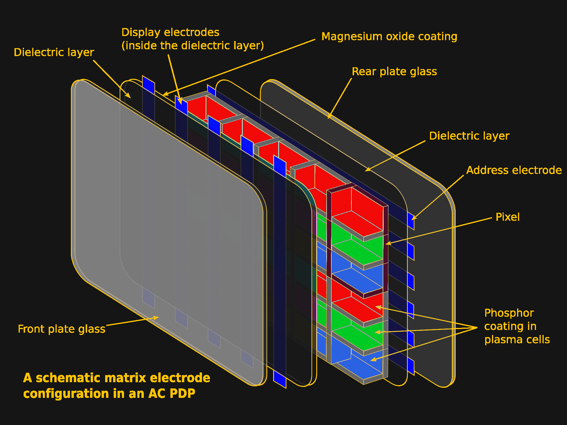
Unlike a CRT, there’s no electron beam scanning the screen, and no shadow mask. Instead, the screen is subdivided into individual pixels inside the flat vacuum panel. The pixels are individually addressed and zapped on and off by an electric current. Unlike a CRT or SED, the voltage here isn’t high enough to generate an electron beam to excite the phosphors; instead the gas discharge inside the display emits enough UV light to do the same job.
Each phosphor-filled pixel glows with its own glorious light thanks to the UV from gas discharge in the cell. Image based on “Plasma-Display-Composition.svg” by [Jari Laamanen].Still, if it feels like a CRT, and that’s because the subpixels are individual blobs of phosphors, excited from behind, and generating their own glorious light.
It’s Not the Same, Though
It’s not a CRT, of course. The biggest difference is that it’s a fixed-pixel display, with all that comes with that. This particular TV has all the ports on the back to make it great for retrogaming, but the NES, or what have you, signal still has to be digitally upscaled to match the resolution. Pixel art goes unblurred by scanlines unless I add it in via emulation, so despite the colour and contrast, it’s not quite the authentic experience.
For some things, like the Atari 2600, the scanline blur really doesn’t matter. Image: “Atari 2600 on my 42 inch plasma TV” by [Jeffisageek] The built-in upscaling doesn’t introduce enough latency for a filthy casual like me to notice, but I’ll never be able to play Duck Hunt on the big screen unless I fake it with a Wii. Apparently some Plasma TVs are awesome for latency on the analog inputs, and others are not much better than an equivalent-era LCD. There’s a reason serious retro gamers pay serious money for big CRTs.
Those big CRTs don’t have to worry about burn in, either, something I have been very careful in the five years I’ve owned this second-hand plasma display to avoid. I can’t remember thinking much about burn-in with CRTs since we retired the amber-phosphor monitor plugged into the Hercules Graphics card on our family’s 286 PC.
The dreaded specter of burn-in is plasma’s Achilles heel – more than the weight and thickness, which were getting much better before LG pulled the plug as the last company to exit this space, or the Energy Star ratings, which weren’t going to catch up to LED-backlit LCDs, but had improved as well. The fear of burn-in made you skip the plasma, especially for console gaming.
This screen is haunted by the ghost of CNN’s old logo. Burning in game graphics was less common but more fun. Ironically, it’s an LCD. Image: “logo of CNN burnt on a screen” by [Nate]Early plasma displays could permanently damage the delicate phosphors in only a handful of hours. That damage burnt the unmoving parts of an image permanently into the phosphors in the form of “ghosting”, and unless you caught it early, it was generally not repairable. The ghosting issue got better over time, but the technology never escaped the stigma, and the problem never entirely went away. If that meant that after a marathon Call-of-Duty session the rest of the family had to stare at your HUD on every movie night, Dad wasn’t going to buy another plasma display.
By the end, the phosphors improved and various tricks like jiggling the image pixel-by-pixel were found to avoid burn-in, and it seems to have worked: there’s absolutely no ghosting on my model, and you can sometimes find late-model Plasma TVs for the low, low cost of “get this thing off my wall and up the stairs” that are equally un-haunted. I may grab another, even if I have to pay for it. It’s a lot easier to hide a spare flatscreen than an extra CRT, another advantage to the plasma TVs, and in no case do phosphors last forever.
In the mean time, I’m going to enjoy the contrast ratio, refresh rate, and the bonus space heater. I’m in Canada, and winter is coming, so it’s hard to get too overworked about waste heat when there’s frost on your windowpanes.
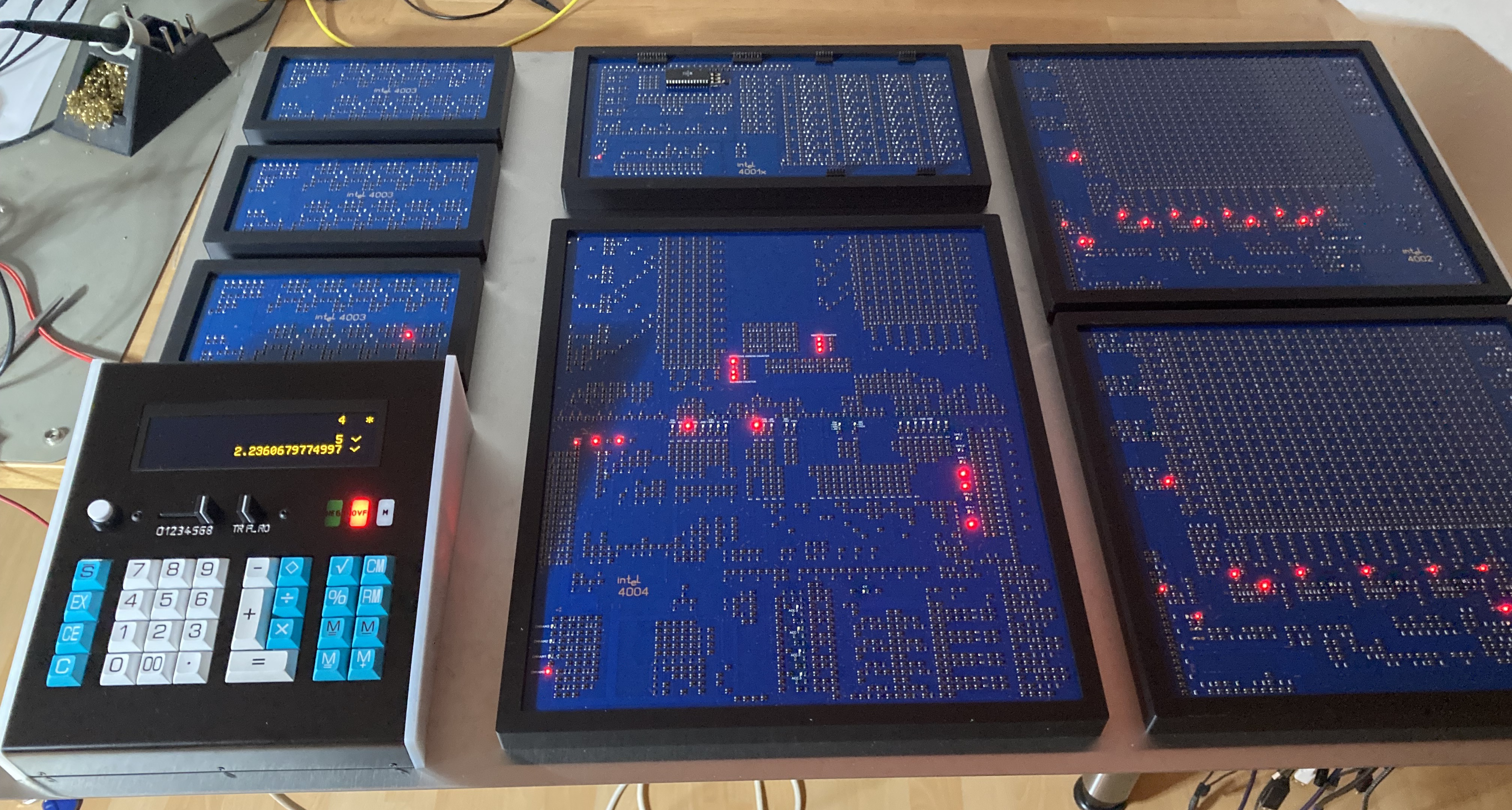
Though mobile devices and Apple Silicon have seen ARM-64 explode across the world, there’s still decent odds you’re reading this on a device with an x86 processor — the direct descendant of the world’s first civilian microprocessor, the Intel 4004. The 4004 wasn’t much good on its own, however, which is why [Klaus Scheffler] and [Lajos Kintli] have produced super-sized discrete chips of the 4001 ROM, 4002 RAM, and 4003 shift register to replicate a 1970s calculator at 10x the size and double the speed, all in time for the 4004’s 50th anniversary.
We featured this project a couple of years back, when it was just a lonely microprocessor. Adding the other MSC-4 series chips enabled the pair to faithfully reproduce the logic of a Busicom 141-PF calculator, the very first to market with Intel’s now-legendary microprocessor. Indeed, this calculator is the raison d’etre for the 4004: Busicom commissioned the whole Micro-Computer System 4-bit (MCS-4) set of chips specifically for this calculator. Only later, once they realized what they had made, did Intel buy the rights back from the Japanese calculator company, and the rest, as they say, is history.
Since its history, it belongs in a museum– and that’s where this giant, FET-based calculator is going. If you happen to be in Solothurn, Switzerland, you’ll be able to see it at a new history of technology exhibit opening at the Enter Museum in 2026. Do check out the write-up and links at 4004.com if you want to learn about this important piece of human history.
The museum-quality hack. Three 4003 shift registers are on the left, with a 4001 ROM above the 4004 CPU in the center, flanked by three 4002 RAM “chips” on the right. Photo by [Klaus Scheffler].We had to specify “first civilian microprocessor” at the start of this article because the US Navy beat them to the punch by a whole year, and kept it secret until 1998. There’s something very 1970s about the fact that top-secret US military technology was reinvented for a Japanese calculator within a year. It honestly makes [Federico Faggin], the man credited with the design, seem no less visionary than when we thought he was first out of the gate.