We have probably all been there: digging through boxes full of old boards for projects and related parts. Often it’s not because we’re interested in the contents of said box, but because we found ourselves wondering why in the name of project management we have so many boxes of various descriptions kicking about. This is the topic of [Joe Barnard]’s recent video on his BPS.shorts YouTube channel, as he goes through box after box of stuff.
For some of the ‘trash’ the answer is pretty simple; such as the old rocket that’s not too complex and can have its electronics removed and the basic tube tossed, which at least will reduce the volume of ‘stuff’. Then there are the boxes with old projects, each of which are tangible reminders of milestones, setbacks, friendships, and so on. Sentimental stuff, basically.
Some rules exist for safety that make at least one part obvious, and that is that every single Li-ion battery gets removed when it’s not in use, with said battery stored in its own fire-resistant box. That then still leaves box after box full of parts and components that were ordered for projects once, but not fully used up. Do you keep all of it, just in case it will be needed again Some Day? The same issue with boxes full of expensive cut-off cable, rare and less rare connectors, etc.
One escape clause is of course that you can always sell things rather than just tossing it, assuming it’s valuable enough. In the case of [Joe] many have watched his videos and would love to own a piece of said history, but this is not an option open to most. Leaving the question of whether gritting one’s teeth and simply tossing the ‘value-less’ sentimental stuff and cheap components is the way to go.
Although there is always the option of renting storage somewhere, this feels like a cheat, and will likely only result in the volume of ‘stuff’ expanding to fill the void. Ultimately [Joe] is basically begging his viewers to help him to solve this conundrum, even as many of them and our own captive audience are likely struggling with a similar problem. Where is the path to enlightenment here?
Within the retro computing community there exists a lot of controversy about so-called ‘retrobrighting’, which involves methods that seeks to reverse the yellowing that many plastics suffer over time. While some are all in on this practice that restores yellow plastics to their previous white luster, others actively warn against it after bad experiences, such as [Tech Tangents] in a recent video.
Uneven yellowing on North American SNES console. (Credit: Vintage Computing)
After a decade of trying out various retrobrighting methods, he found for example that a Sega Dreamcast shell which he treated with hydrogen peroxide ten years ago actually yellowed faster than the untreated plastic right beside it. Similarly, the use of ozone as another way to achieve the oxidation of the brominated flame retardants that are said to underlie the yellowing was also attempted, with highly dubious results.
While streaking after retrobrighting with hydrogen peroxide can be attributed to an uneven application of the compound, there are many reports of the treatment damaging the plastics and making it brittle. Considering the uneven yellowing of e.g. Super Nintendo consoles, the cause of the yellowing is also not just photo-oxidation caused by UV exposure, but seems to be related to heat exposure and the exact amount of flame retardants mixed in with the plastic, as well as potentially general degradation of the plastic’s polymers.
Pending more research on the topic, the use of retrobrighting should perhaps not be banished completely. But considering the damage that we may be doing to potentially historical artifacts, it would behoove us to at least take a step or two back and consider the urgency of retrobrighting today instead of in the future with a better understanding of the implications.
Hand soldering can be a messy business, especially when you wipe the soldering iron tip on those common brass wool bundles that have largely come to replace moist sponges. The Weller Dry Cleaner (WDC) is one of such holders for brass wool, but the large tray in front of the opening with the brass wool has confused many as to its exact purposes. In short, it’s there so that you can slap the iron against the side to flick contaminants and excess solder off the tip.
Along with catching some of the bits of mostly solder that fly off during cleaning in the brass wool section, quite a lot of debris can be collected this way. Yet as many can attest to, it’s quite easy to flip over brass wool holders and have these bits go flying everywhere.
The trap in action. (Credit: MisterHW)
That’s where [MisterHW]’s pit of particulate holding comes into play, using folded sheet metal and some wax (e.g. paraffin) to create a trap that serves to catch any debris that enters it and smother it in the wax. To reset the trap, simply heat it up with e.g. the iron and you’ll regain a nice fresh surface to capture the next batch of crud.
As the wax is cold when in use, even if you were to tip the holder over, it should not go careening all over your ESD-safe work surface and any parts on it, and the wax can be filtered if needed to remove the particulates. When using leaded solder alloys, this setup also helps to prevent lead-contamination of the area and generally eases clean-up as bumping or tipping a soldering iron stand no longer means weeks, months or years of accumulations scooting off everywhere.
To those of us who live in the civilized lands where ~230 VAC mains is the norm and we can shove a cool 3.5 kW into an electric kettle without so much as a second thought, the mere idea of trying to boil water with 120 VAC and a tepid 1.5 kW brings back traumatic memories of trying to boil water with a 12 VDC kettle while out camping. Naturally, in a fit of nationalistic pride this leads certain North American people like that bloke over at the [Technology Connections] YouTube to insist that this is fine, as he tries to demonstrate how ridiculous 240 VAC kettles are by abusing a North American Level 2 car charger to power a UK-sourced kettle.
Ignoring for a moment that in Europe a ‘Level 1’ charger is already 230 VAC (±10%) and many of us charge EVs at home with three-phase ~440 VAC, this video is an interesting demonstration, both of how to abuse an EV car charger for other applications and how great having hot water for tea that much faster is.
Friendly tea-related transatlantic jabs aside, the socket adapter required to go from the car charger to the UK-style plug is a sight to behold. All which we starts as we learn that Leviton makes a UK-style outlet for US-style junction boxes, due to Gulf States using this combination. This is subsequently wired to the pins of the EV charger connector, after which the tests can commence.
Unsurprisingly, the two US kettles took nearly five minutes to boil the water, while the UK kettle coasted over the finish line at under two minutes, allowing any tea drinker to savor the delightful smells of the brewing process while their US companion still stares forlornly at their American Ingenuity in action.
Beginning to catch the gist of why more power now is better, the two US kettles were then upgraded to a NEMA 6-20 connector, rated for 250 VAC and 20 A, or basically your standard UK ring circuit outlet depending on what fuse you feel bold enough to stick into the appliance’s power plug. This should reduce boiling time to about one minute and potentially not catch on fire in the process.
Both of the kettles barely got a chance to overheat and boiled the water in 55 seconds. Unfortunately only the exposed element kettle survived multiple runs, and both found themselves on an autopsy table as it would seem that these kettles are not designed to heat up so quickly. Clearly a proper fast cup of tea will remain beyond reach of the average North American citizen beyond sketchy hacks or using an old-school kettle.
As amazing as the human body is, it’s unfortunately not as amazing as e.g. axolotl bodies are, in the sense that they can regrow entire limbs and more. This has left us humans with the necessity to craft artificial replacement limbs to restore some semblance of the original functionality, at least until regenerative medicine reaches maturity.
Despite this limitation, humans have become very adept at crafting prosthetic limbs, starting with fairly basic prosthetics to fully articulated and beautifully sculpted ones, all the way to modern-day functional prosthetics. Yet as was the case a hundred years ago, today’s prosthetics are anything but cheap. This is mostly due to the customization required as no person’s injury is the same.
When the era of 3D printing arrived earlier this century, it was regularly claimed that this would make cheap, fully custom prosthetics a reality. Unfortunately this hasn’t happened, for a variety of reasons. This raises the question of whether 3D printing can at all play a significant role in making prosthetics more affordable, comfortable or functional.
The requirements for a prosthetic depend on the body part that’s affected, and how much of it has been lost. In the archaeological record we can find examples of prosthetics dating back to around 3000 BCE in Ancient Egypt, in the form of prosthetic toes that likely were mostly cosmetic. When it came to leg prosthetics, these would usually be fashioned out of wood, which makes the archaeological record here understandably somewhat spotty.
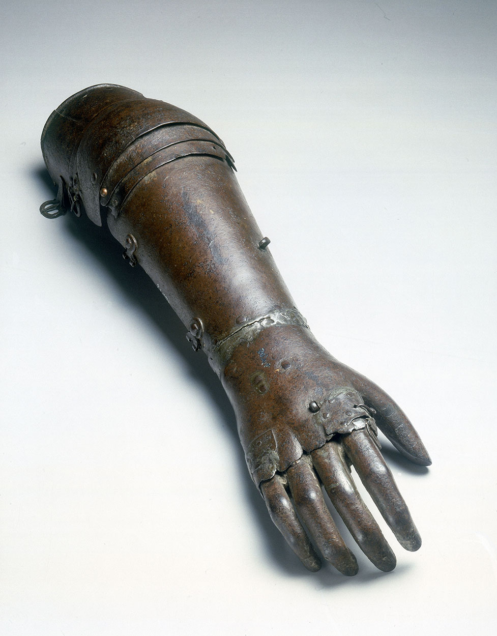
Artificial iron arm, once thought to have been owned by Gotz von Berlichingen (1480-1562). (Credit: Mr John Cummings, Wikimedia)
While Pliny the Elder made mention of prosthetics like an iron hand for a general, the first physical evidence of a prosthetic for a lost limb are found in the form of items such as the Roman Capua Leg, made out of metal, and a wooden leg found with a skeleton at the Iron Age-era Shengjindian cemetery that was dated to around 300 BCE. These prosthetics were all effectively static, providing the ability to stand, walk and grip items, but truly functional prosthetics didn’t begin to be developed until the 16th century.
These days we have access to significantly more advanced manufacturing methods and materials, 3D scanners, and the ability to measure the electric currents produced by muscles to drive motors in a prosthetic limb, called myoelectric control. This latter control method can be a big improvement over the older method whereby the healthy opposing limb partially controls the body-powered prosthetic via some kind of mechanical system.
All of this means that modern-day prosthetics are significantly more complex than a limb-shaped piece of wood or metal, giving some hint as to why 3D printing may not produce quite the expected savings. Even historically, the design of functional prosthetic limbs involved complex, fragile mechanisms, and regardless of whether a prosthetic leg was just static or not, it would have to include some kind of cushioning that matched the function of the foot and ankle to prevent the impact of each step to be transferred straight into the stump. After all, a biological limb is much more than just some bones that happen to have muscles stuck to them.
Making It Fit
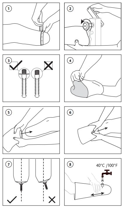
Fitting and care instructions for cushioning and locking prothesis liners. (Credit: Össur)
Perhaps the most important part of a prosthetic is the interface with the body. This one element determines the comfort level, especially with leg prostheses, and thus for how long a user can wear it without discomfort or negative health impacts. The big change here has been largely in terms of available materials, with plastics and similar synthetics replacing the wood and leather of yesteryear.
Generally, the first part of fitting a prosthetic limb involves putting on the silicone liner, much like one would put on a sock before putting on a shoe. This liner provides cushioning and creates an interface with the prosthesis. For instance, here is an instruction manual for just such a liner by Össur.
These liners are sized and trimmed to fit the limb, like a custom comfortable sock. After putting on the liner and adding an optional distal end pad, the next step is to put on the socket to which the actual prosthetic limb is attached. The fit between the socket and liner can be done with a locking pin, as pictured on the right, or in the case of a cushion liner by having a tight seal between the liner and socket. Either way, the liner and socket should not be able to move independently from each other when pulled on — this movement is called “pistoning”.
For a below-knee leg prosthesis the remainder of the device below the socket include the pylon and foot, all of which are fairly standard. The parts that are most appealing for 3D printing are this liner and the socket, as they need to be the most customized for an individual patient.
Companies like the US-based Quorum Prosthetics do in fact 3D print these sockets, and they claim that it does reduce labor cost compared to traditional methods, but their use of an expensive commercial 3D printer solution means that the final cost per socket is about the same as using traditional methods, even if the fit may be somewhat better.
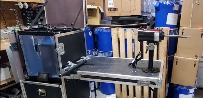
The luggable Limbkit system, including 3D printer and workshop. (Credit: Operation Namaste)
This highlights perhaps the most crucial point about using 3D printing for prosthetics: to make it truly cheaper you also have to lean into lower-tech solutions that are accessible to even hobbyists around the world. This is what for example Operation Namaste does, with 3D printed molds for medical grade silicone to create liners, and their self-contained Limbkit system for scanning and printing a socket on the spot in PETG. This socket can be then reinforced with fiberglass and completed with the pylon and foot, creating a custom prosthetic leg in a fraction of the time that it would typically take.
Founder of Operation Namaste, Jeff Erenstone, wrote a 2023 article on the hype and reality with 3D printed prosthetics, as well as how he got started with the topic. Of note is that the low-cost methods that his Operation Namaste brings to low-resource countries in particular are not quite on the same level as a prosthetic you’d get fitted elsewhere, but they bring a solution where previously none existed, at a price point that is bearable.
Merging this world with that of of Western medical systems and insurance companies is definitely a long while off. Additive manufacturing is still being tested and only gradually integrated into Western medical systems. At some level this is quite understandable, as it comes with many asterisks that do not exist in traditional manufacturing methods.
It probably doesn’t bear reminding that having an FDM printed prosthetic snap or fracture is a far cry from having a 3D printed widget do the same. You don’t want your bones to suddenly go and break on you, either, and faulty prosthetics are a welcome source of expensive lawsuits in the West for lawyers.
Making It Work
Beyond liners and sockets there is much more to prosthetic limbs, as alluded to earlier. Myoelectric control in particular is a fairly recent innovation that detects the electrical signals from the activation of skeletal muscles, which are then used to activate specific motor functions of a prosthetic limb, as well as a prosthetic hand.
The use of muscle and nerve activity is the subject of a lot of current research pertaining to prosthetics, not just for motion, but also for feedback. Ideally the same nerves that once controlled the lost limb, hand or finger can be reused again, along with the nerves that used to provide a sense of touch, of temperature and more. Whether this would involve surgical interfacing with said nerves, or some kind of brain-computer interface is still up in the air.
How this research will affect future prosthetics remains to be seen, but it’s quite possible that as artificial limbs become more advanced, so too will the application of additive manufacturing in this field, as the next phase following the introduction of plastics and other synthetic materials.
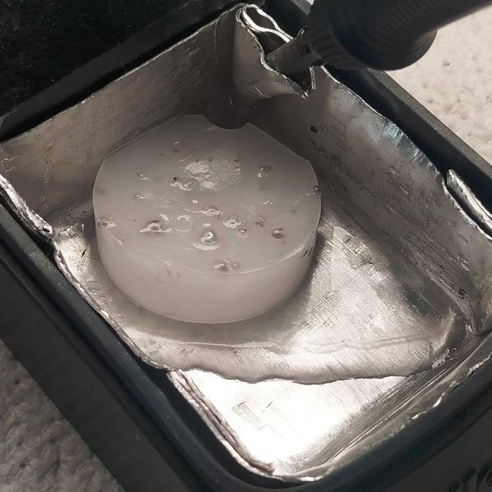
Closed-cell self-expanding foam (spray foam) is an amazing material that sees common use in construction. But one application that we hadn’t heard of before was using it to fill the internal voids of 3D printed objects. As argued by [Alex] in a half-baked-research YouTube video, this foam could be very helpful with making sure that printed boats keep floating and water stays out of sensitive electronic bits.
It’s pretty common knowledge by now that 3D printed objects from FDM printers aren’t really watertight. Due to the way that these printers work, there’s plenty of opportunity for small gaps and voids between layers to permit moisture to seep through. This is where the use of this self-expanding foam comes into play, as it’s guaranteed to be watertight. In addition, [Alex] also tests how this affects the strength of the print and using its insulating properties.
The test prints are designed with the requisite port through which the spray foam is injected as well as pressure relief holes. After a 24 hour curing period the excess foam is trimmed. Early testing showed that in order for the foam to cure well inside the part, it needed to be first flushed with water to provide the moisture necessary for the chemical reaction. It’s also essential to have sufficient pressure relief holes, especially for the larger parts, as the expanding foam can cause structural failure.
As for the results, in terms of waterproofing there was some water absorption, likely in the PETG part. But after 28 hours of submerging none of the sample cubes filled up with water. The samples did not get any stronger tensile-wise, but the compression test showed a 25 – 70% increase in resistance to buckling, which is quite significant.
Finally, after tossing some ice cubes into a plain FDM printed box and one filled with foam, it took less than six hours for the ice to melt, compared to the spray foam insulated box which took just under eight hours.
This seems to suggest that adding some of this self-expanding foam to your 3D printed part makes a lot of sense if you want to keep water out, add more compressive strength, or would like to add thermal insulation beyond what FDM infill patterns can provide.
As the saying goes: if it has a processor and a display, it can run DOOM. The corollary here is that if some software displays things, someone will figure out a way to make it render the iconic shooter. Case in point KiDoom by [Mike Ayles], which happily renders DOOM in KiCad at a sedate 10 to 25 frames per second as you blast away at your PCB routing demons.
Obviously, the game isn’t running directly in KiCad, but it does use the doomgenericDOOM engine in a separate process, with KiCad’s PCB editor handling the rendering. As noted by [Mike], he could have used a Python version of DOOM to target KiCad’s Python API, but that’s left as an exercise for the reader.
Rather than having the engine render directly to a display, [Mike] wrote code to extract the position of sprites and wall segments, which is then sent to KiCad via its Python interface, updating the view and refreshing the ‘PCB’. Controls are as usual, though you’ll be looking at QFP-64 package footprints for enemies, SOIC-8 for decorations and SOT-23-3 packages for health, ammo and keys.
If you’re itching to give it a try, the GitHub project can be found right here. Maybe it’ll bring some relief after a particularly frustrating PCB routing session.
Antihydrogen forms an ideal study subject for deciphering the secrets of fundamental physics due to it being the most simple anti-matter atom. However, keeping it from casually annihilating itself along with some matter hasn’t gotten much easier since it was first produced in 1995. Recently ALPHA researchers at CERN’s Antimatter Factory announced that they managed to produce and trap no fewer than 15,000 antihydrogen atoms in less than seven hours using a new beryllium-enhanced trap. This is an eight-fold increase compared to previous methods.
To produce an antihydrogen atom from a positron and an antiproton, the components and resulting atoms can not simply be trapped in an electromagnetic field, but requires that they are cooled to the point where they’re effectively stationary. This also makes adding more than one of such atom to a trap into a tedious process since the first successful capture in 2017.
In the open access paper in Nature Communications by [R. Akbari] et al. the process is described, starting with the merging of anti-protons from the CERN Antiproton Decelerator with positrons sourced from the radioactive decay of sodium-22 (β+ decay). The typical Penning-Malmberg trap is used, but laser-cooled beryllium ions (Be+) are added to provide sympathetic cooling during the synthesis step.
Together with an increased availability of positrons, the eight-fold increase in antihydrogen production was thus achieved. The researchers speculate that the sympathetic cooling is more efficient at keeping a constant temperature than alternative cooling methods, which allows for the increased rate of production.
Intel’s 386 CPU is notable for being its first x86 CPU to use so-called standard cell logic, which swapped the taping out of individual transistors with wiring up standardized functional blocks. This way you only have to define specific gate types, latches and so on, after which a description of these blocks can be parsed and assembled by a computer into elements of a functioning application-specific integrated circuit (ASIC). This is standard procedure today with register-transfer level (RTL) descriptions being placed and routed for either an FPGA or ASIC target.
That said, [Ken Shirriff] found a few surprises in the 386’s die, some of which threw him for a loop. An intrinsic part of standard cells is that they’re arranged in rows and columns, with data channels between them where signal paths can be routed. The surprise here was finding a stray PMOS transistor right in the midst of one such data channel, which [Ken] speculates is a bug fix for one of the multiplexers. Back then regenerating the layout would have been rather expensive, so a manual fix like this would have made perfect sense. Consider it a bodge wire for ASICs.
Another oddity was an inverter that wasn’t an inverter, which turned out to be just two separate NMOS and PMOS transistors that looked to be wired up as an inverter, but seemed to actually there as part of a multiplexer. As it turns out, it’s hard to determine sometimes whether transistors are connected in these die teardowns, or whether there’s a gap between them, or just an artifact of the light or the etching process.
The cool part about science is that you can ask questions like what happens if you stick some moss spores on the outside of the International Space Station, and then get funding for answering said question. This was roughly the scope of the experiment that [Chang-hyun Maeng] and colleagues ran back in 2022, with their findings reported in iScience.
Used as moss specimen was Physcomitrium patens, a very common model organism. After previously finding during Earth-based experiments that the spores are the most resilient, these were subsequently transported to the ISS where they found themselves placed in the exposure unit of the Kibo module. Three different exposure scenarios were attempted for the spores, with all exposed to space, but one set kept in the dark, another protected from UV and a third set exposed to the healthy goodness of the all-natural UV that space in LEO has to offer.
After the nine month exposure period, the spores were transported back to Earth, where the spores were allowed to develop into mature P. patens moss. Here it was found that only the spores which had been exposed to significant UV radiation – including UV-C unfiltered by the Earth’s atmosphere – saw a significant reduction in viability. Yet even after nine months of basking in UV-C, these still had a germination rate of 86%, which provides fascinating follow-up questions regarding their survivability mechanisms when exposed to UV-C as well as a deep vacuum, freezing temperatures and so on.
Today’s pressurized water reactors (PWRs) are marvels of nuclear fission technology that enable gigawatt-scale power stations in a very compact space. Though they are extremely safe, with only the TMI-2 accident releasing a negligible amount of radioactive isotopes into the environment per the NRC, the company Deep Fission reckons that they can make PWRs even safer by stuffing them into a 1 mile (1.6 km) deep borehole.
Their proposed DB-PWR design is currently in pre-application review at the NRC where their whitepaper and 2025-era regulatory engagement plan can be found as well. It appears that this year they renamed the reactor to Deep Fission Borehole Reactor 1 (DFBR-1). In each 30″ (76.2 cm) borehole a single 45 MWt DFBR-1 microreactor will be installed, with most of the primary loop contained within the reactor module.
As for the rationale for all of this, at the suggested depth the pressure would be equivalent to that inside the PWR, with in addition a column of water between it and the surface, which is claimed to provide a lot of safety and also negates the need for a concrete containment structure and similar PWR safety features. Of course, with the steam generator located at the bottom of the borehole, said steam has to be brought up all the way to the surface to generate a projected 15 MWe via the steam turbine, and there are also sampling tubes travelling all the way down to the primary loop in addition to ropes to haul the thing back up for replacing the standard LEU PWR fuel rods.
Whether this level of outside-the-box-thinking is a genius or absolutely daft idea remains to be seen, with it so far making inroads in the DoE’s advanced reactor program. The company targets having its first reactor online by 2026. Among its competition are projects like TerraPower’s Natrium which are already under construction and offer much more power per reactor, along with Natrium in particular also providing built-in grid-level storage.
One thing is definitely for certain, and that is that the commercial power sector in the US has stopped being mind-numbingly boring.
That MacOS (formerly OS X) has BSD roots is a well-known fact, with its predecessor NeXTSTEP and its XNU kernel derived from 4.3BSD. Subsequent releases of OS X/MacOS then proceeded to happily copy more bits from 4.4BSD, FreeBSD and other BSDs.
In that respect the thing that makes MacOS unique compared to other BSDs is its user interface, which is what the open source ravynOS seeks to address. By taking FreeBSD as its core, and crafting a MacOS-like UI on top, it intends to provide the MacOS UI experience without locking the user into the Apple ecosystem.
Although FreeBSD already has the ability to use the same desktop environments as Linux, there are quite a few people who prefer the Apple UX. As noted in the project FAQ, one of the goals is also to become compatible with MacOS applications, while retaining support for FreeBSD applications and Linux via the FreeBSD binary compatibility layer.
If this sounds good to you, then it should be noted that ravynOS is still in pre-release, with the recently released ravynOS “Hyperpop Hyena” 0.6.1 available for download and your perusal. System requirements include UEFI boot, 4+ GB of RAM, x86_x64 CPU and either Intel or AMD graphics. Hardware driver support for the most part is that of current FreeBSD 14.x, which is generally pretty decent on x86 platforms, but your mileage may vary. For testing systems and VMs have a look at the supported device list, and developers are welcome to check out the GitHub page for the source.
Considering our own recent coverage of using FreeBSD as a desktop system, ravynOS provides an interesting counterpoint to simply copying over the desktop experience of Linux, and instead cozying up to its cousin MacOS. If this also means being able to run all MacOS games and applications, it could really propel FreeBSD into the desktop space from an unexpected corner.
The history of the game Zork is a long and winding one, starting with MUDs and kin on university mainframes – where students entertained themselves in between their studies – and ending with the game being ported to home computers. These being pathetically undersized compared to even a PDP-10 meant that Zork got put to the axe, producing Zork I through III. Originally distributed by Infocom, eventually the process of Microsoft gobbling up game distributors and studios alike meant that Microsoft came to hold the license to these games. Games which are now open source as explained on the Microsoft Open Source blog.
Although the source had found its way onto the Internet previously, it’s now officially distributed under the MIT license, along with accompanying developer documentation. The source code for the three games can be found on GitHub, in separate repositories for Zork I, Zork II and Zork III.
We previously covered Zork’s journey from large systems to home computers, which was helped immensely by the Z-machine platform that the game’s code was ported to. Sadly the original games’s MDL code was a bit much for 8-bit home computers. Regardless of whether you prefer the original PDP-10 or the Z-machine version on a home computer system, both versions are now open sourced, which is a marvelous thing indeed.
On November 18 of 2025 a large part of the Internet suddenly cried out and went silent, as Cloudflare’s infrastructure suffered the software equivalent of a cardiac arrest. After much panicked debugging and troubleshooting, engineers were able to coax things back to life again, setting the stage for the subsequent investigation. The results of said investigation show how a mangled input file caused an exception to be thrown in the Rust-based FL2 proxy which went uncaught, throwing up an HTTP 5xx error and thus for the proxy to stop proxying customer traffic. Customers who were on the old FL proxy did not see this error.
The input file in question was the features file that is generated dynamically depending on the customer’s settings related to e.g. bot traffic. A change here resulted in said feature file to contain duplicate rows, increasing the number of typical features from about 60 to over 200, which is a problem since the proxy pre-allocates memory to contain this feature data.
While in the FL proxy code this situation was apparently cleanly detected and handled, the new FL2 code happily chained the processing functions and ingested an error value that caused the exception. This cascaded unimpeded upwards until panic set in: thread fl2_worker_thread panicked: called Result::unwrap() on an Err value
The Rust code in question was the following:
The obvious problem here is that an error condition did not get handled, which is one of the most basic kind of errors. The other basic mistake seems to be that of input validation, as apparently the oversized feature file doesn’t cause an issue until it’s attempted to stuff it into the pre-allocated memory section.
As we have pointed out in the past, the biggest cause of CVEs and similar is input validation and error handling. Just because you’re writing in a shiny new language that never misses an opportunity to crow about how memory safe it is, doesn’t mean that you can skip due diligence on input validation, checking every return value and writing exception handlers for even the most unlikely of situations.
We hope that Cloudflare has rolled everyone back to the clearly bulletproof FL proxy and is having a deep rethink about doing a rewrite of code that clearly wasn’t broken.
When you’re like [Wes] from Watch Wes Work fame, you don’t have a CNC machine hoarding issue, you just have a healthy interest in going down CNC machine repair rabbit holes. Such too was the case with a recently acquired 2001 Milltronics ML15 lathe, that at first glance appeared to be in pristine condition. Yet despite – or because of – living a cushy life at a college’s workshop, it had a number of serious issues, with a busted Z-axis drive board being the first to be tackled.
The Glentek servo board that caused so much grief. (Credit: Watch Wes Work, YouTube)
The identical servo control board next to it worked fine, so it had to be an issue on the board itself. A quick test showed that the H-bridge IGBTs had suffered the typical fate that IGBTs suffer, violently taking out another IC along with them. Enjoyably, this board by one Glentek Inc. did the rebranding thing of components like said IGBTs, which made tracking down suitable replacements an utter pain that was eased only by the desperate communications on forums which provided some clues. Of course, desoldering and testing one of the good IGBTs on the second board showed the exact type of IGBT to get.
After replacing said IGBTs, as well as an optocoupler and other bits and pieces, the servo board was good as new. Next, the CNC lathe also had a busted optical encoder, an unusable tool post and a number of other smaller and larger issues that required addressing. Along the way the term ‘pin-to-pin compatible’ for a replacement driver IC was also found to mean that you still have to read the full datasheet.
Of the whole ordeal, the Glentek servo board definitely caused the most trouble, with the manufacturer providing incomplete schematics, rebranding parts to make generic replacements very hard to find and overall just going for a design that’s interesting but hard to diagnose and fix. To help out anyone else who got cursed with a Glentek servo board like this, [Wes] has made the board files and related info available in a GitHub repository.
Amidst the glossy marketing for VPN services, it can be tempting to believe that the moment you flick on the VPN connection you can browse the internet with full privacy. Unfortunately this is quite far from the truth, as interacting with internet services like websites leaves a significant fingerprint. In a study by [RTINGS.com] this browser fingerprinting was investigated in detail, showing just how easy it is to uniquely identify a visitor across the 83 laptops used in the study.
As summarized in the related video (also embedded below), the start of the study involved the Am I Unique? website which provides you with an overview of your browser fingerprint. With over 4.5 million fingerprints in their database as of writing, even using Edge on Windows 10 marks you as unique, which is telling.
In the study multiple VPN services were used, each of which resulted in exactly the same fingerprint hash. This is based on properties retrieved from the browser, via JavaScript and other capabilities exposed by the browser, including WebGL and HTML5 Canvas.
Next in the experiment the set of properties used was restricted to those that are more deterministic, removing items such as state of battery charge, and creating a set of 28 properties. This still left all 83 work laptops at the [RTINGS.com] office with a unique fingerprint, which is somewhat amazing for a single Canadian office environment since they should all use roughly the same OS and browser configuration.
As for ways to reduce your uniqueness, browsers like Brave try to mix up some of these parameters used for fingerprinting, but with Brave being fairly rare the use of this browser by itself makes for a pretty unique identifier. Ultimately being truly anonymous on the internet is pretty hard, and thus VPNs are mostly helpful for getting around region blocks for streaming services, not for obtaining more privacy.
The fun part about a programming language like C is that although the language doesn’t directly support many features including object-oriented programming and generics, there’s nothing that’s keeping you from implementing said features in C. This extends to something like type-safe generics in C, as [Raph] demonstrates in a blog post.
After running through the various ways that generics are also being implemented using methods including basic preprocessor macros and void pointers, the demonstrated method is introduced. While not necessarily a new one, the advantage with this method is that it is type-safe. Much like C++ templates, these generics are evaluated at compile time, with the preprocessor handling both the type checking and filling in of the right template snippets.
While somewhat verbose, it can be condensed into a single header file, doesn’t rely on the void type or pointers and can be deduplicated by the linker, preventing bloat. If generics is what you are looking for in your C project, this might be a conceivable solution.
The infrared transceiver installed on the washing machine. (Credit: Severin)
Since modern household appliances now have an MCU inside, they often have a diagnostic interface and — sometimes — more. Case in point: Miele washing machines, like the one that [Severin] recently fixed, leading to the firmware becoming unhappy and refusing to work. This fortunately turned out to be recoverable by clearing the MCU’s fault memory, but if you’re unlucky, you will have to recalibrate the machine, which requires very special and proprietary software.
Naturally, this led [Severin] down the path of investigating how exactly the Miele Diagnostic Utility (MDU) and the Program Correction (PC) interface communicate. Interestingly, the PC interface uses an infrared LED/receiver combination that’s often combined with a status LED, as indicated by a ‘PC’ symbol. This interface uses the well-known IrDA standard, but [Severin] still had to track down the serial protocol.
Research started with digging into a spare 2010-era Miele EDPW 206 controller board with the 65C02-like Mitsubishi 740 series of 8-bit MCUs. These feature a mask ROM for the firmware, so no easy firmware dumping. Fortunately, the Miele@Home ‘smart appliance’ feature uses a module that communicates via UART with the MCU, using a very similar protocol, including switching from 2400 to 9600 baud after a handshake. An enterprising German user had a go at reverse-engineering this Miele@Home serial protocol, which proved to be incredibly useful here.
What is annoying is that the PC interface requires a special unlock sequence, which was a pain to figure out. Fortunately, the SYNC pin on the MCU’s pins for (here unused) external memory was active. It provided insight in which code path was being followed, making it much easier to determine the unlock sequence. As it turned out, 11 00 00 02 13 were the magic numbers to send as the first sequence.
After this, [Severin] was able to try out new commands, including 30 which, as it turns out, can be used to dump the mask ROM. This enabled the creation of a DIY transceiver you can tape to a fully assembled washing machine, for testing. As of now, the next target is a Miele G651 I Plus-3 dishwasher, which annoyingly seems to use a different unlock key.
Of course, you can just trash the electronics and roll your own. That happens more often than you might think.
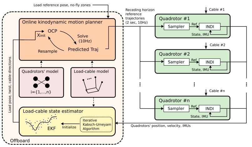
Much like calling over a buddy or two to help with moving a large piece of furniture and pivot it up a narrow flight of stairs, so too can quadcopters increase their carrying capacity through the power of friendship and cooperation. However, unless you want to do a lot of yelling at your mates about when to pivot and lift, you’d better make sure that your coordination is up to snuff. The same is true with quadcopters, where creating an efficient coordination algorithm for sharing a load is far from easy and usually leads to fairly slow and clumsy maneuvering.
Simplified overview of the motion planner by Sihao Sun et al.
Recently. researchers at the Technical University of Delft came up with what appears to be a quite efficient algorithm for this purpose. In the demonstration video below, it’s easy to see how the quadcopters make short work of even convoluted obstacles while keeping themselves and their mates from getting tangled.
The research by [Sihao Sun] et al. appears in Science Robotics (preprint), in which they detail their trajectory-based framework and its kinodynamic motion planner. In short, this planner considers the whole-body dynamics of the load, the cables, and the quadcopters. An onboard controller for each quadcopter is responsible for translating the higher-level commands into specific changes to its rotor speeds and orientation.
Along with tests of its robustness to various environmental factors, such as wind, the researchers experimented with how many simultaneous quadcopters could work together with their available computing capacity. The answer, so far, is nine units, though they think that the implementation can be further optimized.
Vintage computer hardware can fail in a variety of fascinating ways, with [Bits und Bolts] dealing with an interesting failure mode, in the form of degraded MLCC capacitors on Voodoo 2 graphics cards. These little marvels of miniaturized surface-mount technology enable the placement of ceramic capacitors with very little space required, but as they degrade over time or due to physical damage, they can cause big issues in a circuit.
In the case of the two Voodoo 2 GPUs that [Bits und Bolts] was trying to fix, the clue that something was wrong was graphical glitches, which seemed to be related to something dragging down the 5V rail. Using the standard ‘inject voltage and see what gets hot’ method, he discovered a couple of dead MLCCs and replaced them. But something was still dragging the rail down. Unfortunately, whatever it was wasn’t enough to heat up the part in question, and no sane person wants to desolder hundreds or even thousands of MLCCs on a PCB and see whether it makes a difference.
Ultimately, the pyroelectric effect was used to hunt down the culprit, saving countless hours of work. This is a property of certain naturally electrically polarized crystals, in which the material generates a voltage when heated or cooled. Materials like that used in MLCCs, for example.
With a hot air gun set to 200 °C and aimed at a specific MLCC, it was possible to measure changes not only in resistivity but also in voltage between the 5V rail and ground. The voltage spike was relatively minor for the smaller MLCCs, but the larger ones showed a significant voltage swing of around 2.5mV.
The culprit turned out to be a large MLCC, which showed only a weak pyroelectric effect and a resistivity that didn’t drop as quickly as that of similar MLCCs on the same board. After replacement, the faulty MLCC did indeed measure as faulty, and the card’s 5V rail now showed a healthy resistance level to ground.
In addition to knowing what kind of resistivity you should measure on a PCB’s voltage rails relative to ground, this method provides a fairly painless way to quickly find a dodgy MLCC. Just make sure not to try this method on electrolytic or tantalum. Heating those up won’t go well.
We often treat decoupling capacitors as more art than science, but of course, we shouldn’t. MLCCs can even exhibit the piezoelectric effect, too.