❌

Reading view

There are new articles available, click to refresh the page.

Repair and Reverse-Engineering of Nespresso Vertuo Next Coffee Machines

Well there’s your problem. (Credit: Mark Funeaux, YouTube)

Akin to the razor-and-blades model, capsule-based coffee machines are an endless grind of overpriced pods and cheaply made machines that you’re supposed to throw out and buy a new one of, just so that you don’t waste all the proprietary pods you still have at home. What this also means is a seemingly endless supply of free broken capsule coffee makers that might be repairable. This is roughly how [Mark Furneaux] got into the habit of obtaining various Nespresso VertuoLine machines for attempted repairs.

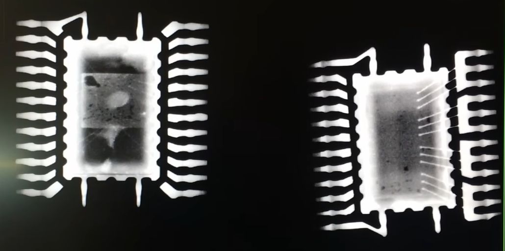
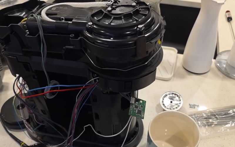
The VirtuoLine machines feature the capsule with a bar code printed on the bottom of the lip, requiring the capsule to be spun around so that it can be read by the optical reader. Upon successful reading, the code is passed to the MCU after which the brewing process is either commenced or cruelly halted if the code fails. Two of the Vertuo Next machines that [Mark] got had such capsule reading errors, leading to a full teardown of the first after the scanner board turned out to work fine.

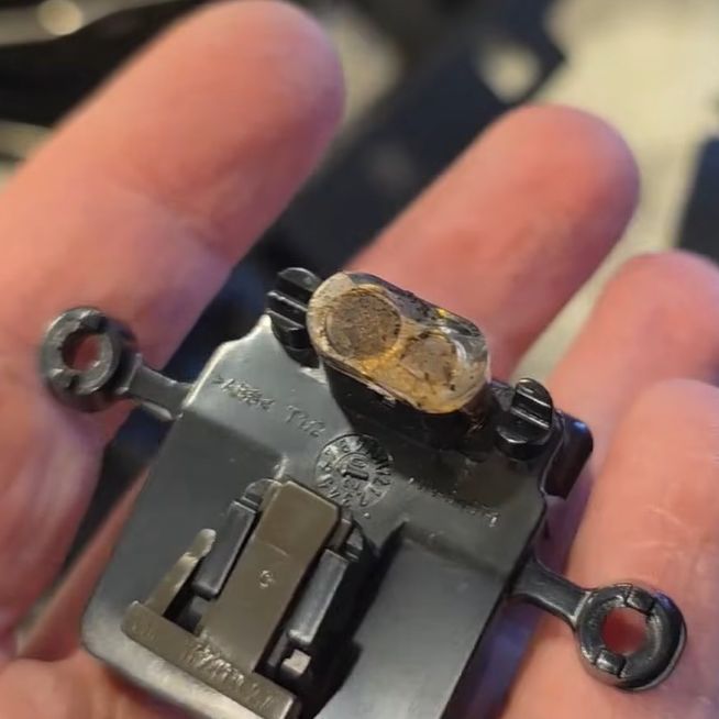
Long story short and many hours of scrubbed footage later, one machine was apparently missing the lens assembly on top of the photo diode and IR LED, while the other simply had these lenses gunked up with spilled coffee. Of course, getting to this lens assembly still required a full machine teardown, making cleaning it an arduous task.

Unfortunately the machine that had the missing lens assembly turned out to have another fault which even after hours of debugging remained elusive, but at least there was one working coffee machine afterwards to make a cup of joe to make [Mark] feel slightly better about his life choices. As for why the lens assembly was missing, it’s quite possible that someone else tried to repair the original fault, didn’t find it, and reassembled the machine without the lens before passing the problem on to the next victim.

The Shelly 2.5 Smart Relay Design Flaw Killing Capacitors

Part of any self-respecting Smart Home, smart relays are useful for switching and monitoring loads that do not plug into an outlet. This also makes them a lot more integrated, and thus, a long lifespan is very welcome. Unfortunately, the popular Shelly 2.5 smart relays seem to be having a bit of a design flaw as they’re dying in droves once their 2-year warranty period is up. The cause and repair are covered in a recent [VoltLog] video on YouTube.

As noted in the Shelly documentation for the device, it’s a very compact form factor device, with screw terminals, two relays, and three fairly large electrolytic capacitors sharing very little space with the rest of the components. The apparent flaw comes in the form of these capacitors failing, with the video showing that one 100 Β΅F capacitor has a massively increased ESR, likely due to electrolyte venting. This results in the observed symptoms, such as WiFi connectivity issues and audible hissing, the latter of which is demonstrated in the video.

Due to the cramped space, the replacement capacitors need to be at least as small as listed in the video and in the top screenshot, though mind the typo as β€˜400Β΅F’ has to be β€˜100Β΅F’. This limitation posed a bit of a problem, as for the two 400V, 4.7 Β΅F capacitors, there aren’t that many options in that form factor. The original capacitors are definitely B- or C-grade ones, with the two large capacitors Chongx branded, being a well-known budget capacitor brand. The other capacitor’s branding cannot be made out in the video, but is likely also Chongx or a similar, less well-regarded Chinese brand.

For the replacements, a Nippon Chemicon capacitor was picked for the 100 Β΅F capacitor, and Ymin-branded capacitors to fit within the size limitations. Picking Ymin over a second Nippon Chemicon set or similar was due to these unfortunate sizing limitations, but these Ymin replacement capacitors had the best datasheet of the options on LCSC. All of these capacitors have to be rated for 105Β°C, for obvious reasons.

Although it’s not easy to say for certain what caused these capacitors to fail so quickly without more data, it seems likely that having the SMPS circuitry for the 3.3V rail bunched up cozily with the three electrolytic capacitors and what looks like two load resistors inside the cramped enclosure with no clear ventilation holes does little to help the electrolytic capacitors hit their listed MTBF hours. Hopefully, using the new capacitors, these relays will last longer than 2-3 years before another recapping is needed.

A New Life For An Old Amplifier

An audio amplifier was once a fairly simple analogue device, but in recent decades a typical home entertainment amplifier will have expanded to include many digital functions. When these break they are often proprietary and not easy to repair, as was the case with a broken Pioneer surround-sound device given to [Boz]. It sat on the shelf for a few years until he had the idea of a jukebox for his ripped CDs, and his returning it to life with a new main board is something to behold.

Internally it’s a surprisingly modular design, meaning that the front panel with its VFD display and driver were intact and working, as were the class AB amplifier and its power supply. He had the service manual so reverse engineering was straightforward, thus out came the main board in favor of a replacement. He took the original connectors and a few other components, then designed a PCB to take them and a Raspberry Pi Pico and DAC. With appropriate MMBASIC firmware it looks as though it was originally made this way, a sense heightened by a look at the motherboard inside (ignoring a couple of bodges).

We like seeing projects like this one which revive broken devices, and this one is particularly special quality wise. We’re more used to seeing it with gaming hardware though.

Fixing a KS Jive DAB Radio with a Dash of Fake ICs

The radio unit after a successful repair. (Credit: Buy it Fix it, YouTube)

The exciting part about repairing consumer electronics is that you are never quite sure what you are going to find. In a recent video by [Mick] of Buy it Fix it on YouTube the subject is a KS Jive radio that throws a few curve balls along the way. After initially seeing the unit not power on with either batteries or external power, opening it up revealed a few loose wires that gave the false hope that it would be an easy fix.

As is typical, the cause of the unit failing appears to have been a power surge that burned out a trace and obliterated the 3.3V LDO and ST TDA7266P amplifier. While the trace was easily fixed, and AMS1117 LDOs are cheap and plentiful, the amplifier chip turned out to be the real challenge on account of being an EOL chip.

The typical response here is to waddle over to purveyors of scrap hardware, like AliExpress sellers. Here [Mick] bought a β€˜new’ TDA7266P, but upon receiving his order, he got suspicious after comparing it with the busted original. As can be seen in the top image, the markings, logo and even typeface are wildly different. Thus [Mick] did what any reasonable person does and x-rayed both chips to compare their internals.

X-ray of the real vs fake ST TDA7266P ICs. (Credit: Buy it Fix it, YouTube)

On the left you can see the dead original amplifier, with what looks like a big mark on the die where the power event destroyed part of it. What’s also apparent from this and the other x-ray shots is that neither the die size, bond wires, nor the physical package’s pins match up. The unusual connections of the fake IC led [Mick] to conclude that it was likely an ST VNQ5E050AK-E quad-channel high-side driver, or at least something very similar to it.

After taking a CNC milling machine to the real and fake chips for additional comparison and a crude decapping, he was still left in a bind, as finding a replacement IC turned out to be basically impossible. Almost, that is, as Mouser turned out to still have the TDA7266P13TR, tape-reel version in stock, with a few left.

This is apparently the same IC, but the cut-reel variety. Interestingly, when tossing this replacement in the x-ray machine, it showed to have a bigger die than the dead ST amplifier IC, which could be due to having been produced with a different process node or so. Regardless, with the original part the radio sprung right back to life, but it shows once again how many chips are being remarked by AliExpress sellers to be something that they are definitely not. Caveat emptor, once more.

Repairing Brittle Plastic Retro Computer Cases

Using UV resin as glue for new case clips. (Credit: More Fun Making It, YouTube)

As computers like the venerable breadbox Commodore 64 age, their plastic doesn’t just turn increasing shades of yellow and brown, the ABS plastic also tends to get brittle. This is a problem that seems to plague many plastic cases and enclosures, but fortunately there are some ways to halt or even reverse the heavy toll of time, with the [More Fun Making It] YouTube channel exploring a number of methods, including UV-curable resin, PETG 3D-printed clips and silicone molds.

Aside from large-scale damage, screw posts tend to snap off a lot, either during shipping or when merely trying to open the case. The same is true for the clips around the edge of the C64 case, which rarely survive that long. Gluing a case clip back on with epoxy or such somewhat works, but is messy and not that durable.

Instead UV resin is used, together with newly printed clips in translucent PETG. The remnants of the old clips are removed, followed by the application of the resin. The clips are actually a modified version of a VIC-20 case clip design by [Ken Mills]. With the UV resin as glue, curing is almost instant with a UV lamp unlike the tedious process with epoxy.

In the case of screw posts the alternative to just re-gluing was initially clear tape as a mold and UV resin, but this got improved with making a mold of an intact post from kitchen-style silicone and corn flour. This mold is placed around the busted post and resin poured in before curing. A new thread can then be created in a drilled-out hole with liquid resin around a screw, though we imagine that one could of course try running a tap through the cured resin as well.

A big challenge for the mold was to create an entire screw post from scratch, which required poring in many layers of resin and curing them, which is probably more tedious than 3D printing a new one. That said, it does seem to work, and it’s not that dissimilar from the resin used with SLA 3D printers, all of which are photopolymers. Without a clear idea of what exact photopolymer is inside the bottle, results may obviously vary.

Finally, resin was also used to try and glue part of the enclosure back together, and a viewer appears to have repaired a terminal whose case got shattered by the tender care of the parcel system using UV resin with good results. Of course, if your system’s case has been basically pulverized as in the case of [LGR]’s laptop, then printing a new case might be the more sensible option.

Thanks to [Petrik77] for the tip.

DIY Grid Dip Meter Teardown

You don’t see them much anymore, but there was a time when any hobbyist who dealt with RF probably had a grid dip meter. The idea was to have an oscillator and measure the grid current as it coupled to external circuits. At resonance, the grid current would go down or dip, hence the name. In the hands of someone who knew how to use it, the meter could measure inductance, capacitance, tuned circuits, antennas, and more. [Thomas] takes a peek inside a homebrew unit from the 1950s in a recent video you can see below.

These meters often have a few things in common. They usually have a plug-in coil near the top and a big tuning capacitor. Of course, there’s also a meter. You have to pick the right coil for the frequency of interest, which both sets the oscillator frequency range and couples to the circuit under test.

The device has an odd case for a homebrew instrument. Whoever made it was an excellent metalworker. Inside was a neatly built circuit with an EC-81 triode and a unique selenium rectifier.

It would be nice to know who the unknown builder was, but with a bit of coaxing, the device still worked just fine. Of course, these days, you have many better options, but it is amazing what all this relatively simple device could do.

We’ve covered how these meters work before, including some pictures from our own benches.

Repairing a Self-Destructing SRS DG535 Digital Delay Generator

There’s a lot of laboratory equipment out there that the casual hobbyist will never need to use, but that doesn’t mean you wouldn’t snap it up if the price is right. That’s what happened when [Tom Verbeure] saw a 1980s digital delay generator at a flea market for $40. Not only is it an excellent way to learn something about these devices, but it also provides a fascinating opportunity to troubleshoot and hopefully fix it. Such was also the case with this Stanford Research Systems (SRS) DG535 that turned out to be not only broken, but even features an apparently previously triggered self-destruct feature.

These devices are pretty basic, with this specimen incorporating a Z80 MPU in addition to digital and analog components to provide a programmable delay with 12.5 nanosecond resolution on its output channels after the input trigger is sensed. For that reason it was little surprise that the problem with the device was with its supply rails, of which a few were dead or out of spec, along with a burned-out trace.

Where the self-destruct feature comes into play is with the use of current boosting resistors around its linear regulators. Although these provide a current boost over what the regulator can provide, their disadvantages include a tendency towards destruction whenever the load on the supply rail decreases. This could for example occur when you’re debugging an issue and leave some of the PCBs disconnected.

Unsurprisingly, this issue caused the same charred trace to reignite during [Tom]’s first repair attempt, but after working up the courage over the subsequent 18 months the second repair attempt went much better, also helped by the presence of the mostly correct original board schematics.

Ultimately the fixes were relatively modest, involving replacing a discrete diode bridge with an integrated one, fixing the -9 V rail with a bodge wire, and replacing the LCD with its busted AC-powered backlight with a modern one with a LED backlight. Fortunately running the 5 V rail at 7 V for a while seemed to have caused no readily observable damage, nor did flipping connectors because of SRS’ inconsistent β€˜standards’ for its connector orientations.

Sadly, when [Tom] emailed SRS to inquire about obtaining an updated schematic for this unit β€” which is currently still being sold new for $4,495 β€” he merely got told to send his unit in for repair.

❌