DIY Magnetic Markers Help 3D Scan Tricky Objects
3D scanners rely on being able to identify physical features of an object, and line up what it saw a moment ago with what it sees now in order to build a 3D model. However, not every object is as distinct and visible as others at all angles, particularly in IR. One solution is reflective scanning markers, which are either pre-printed on a mat, or available as stickers that can be applied to objects to give the scanner a bit more to latch onto, visually speaking.
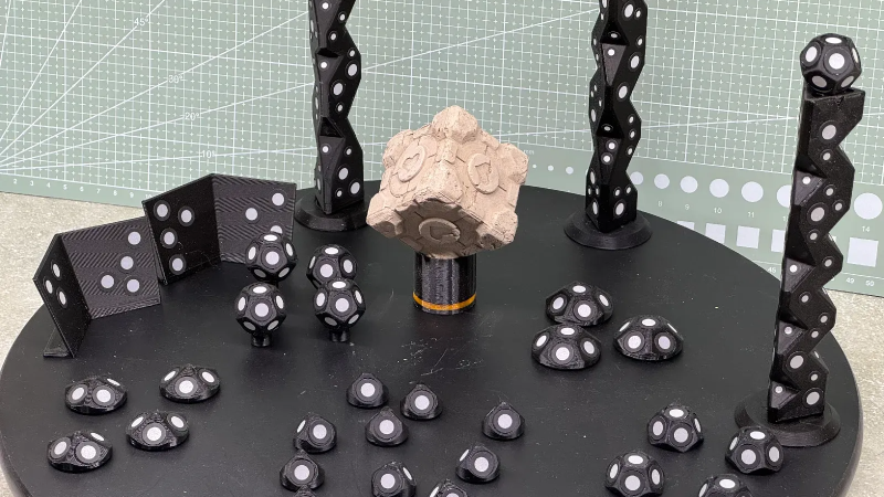
[firstgizmo] shows a slightly different approach: that of surrounding the object to be scanned with 3D printed reflective markers instead of covering the target object itself with reflectors, or relying on a flat scanning mat.
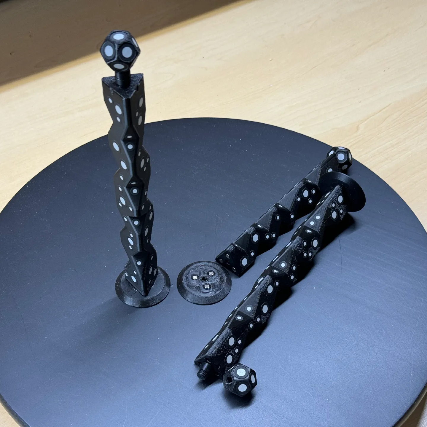
The main advantage (besides not having to remove stickers from the object afterwards) is that these printed markers present the reflective dots at a variety of angles during the scanning process. This makes the scene less sensitive to scanner angle in general, which is good because the angle at which to scan an important feature of an object is not always the angle that responds best.
By giving the scene more structure, the scanner can have a better shot at scanning reliably even if the reflectors aren’t on the target object itself. It also helps by making it easier to combine multiple scans. The more physical features scans have in common, the easier it is to align them.
Just to be clear, using these means one will, in effect, be 3D scanning the markers along with the target object. But once all the post-processing is done, one simply edits the model to remove everything except the target object.
[firstgizmo]’s DIY magnetic 3D scanning markers are an expanded take on an idea first presented by [Payo], who demonstrates the whole concept wonderfully in the video below.
3D scanning can be tremendously handy but it does have its quirks and limitations, and a tool like this can be the difference between a terrible scan and a serviceable one. For a quick catch-up on 3D scanning and its strengths and limitations, read our hands-on tour of using an all-in-one 3D scanner.