Reading view

There are new articles available, click to refresh the page.

Inside a Sketchy Mains Voltage Touch Control Dimmer

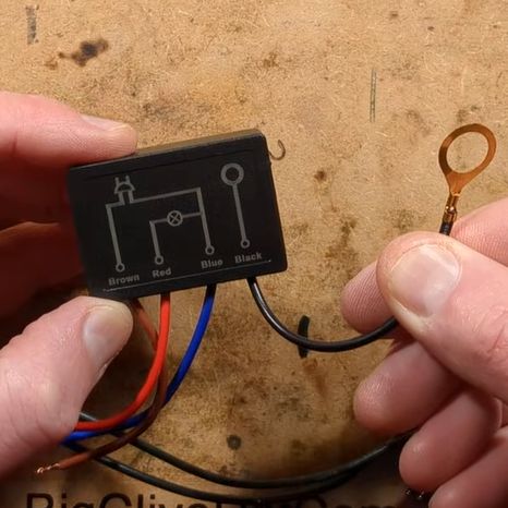
In [Big Clive]’s recent grab bag of tat ordered from Chinese commerce platforms, there were two touch light control boxes that can turn any ungrounded conductive surface into a mains load dimmer control. Of course, the primary reason for the purchase was a teardown, and a teardown we got.

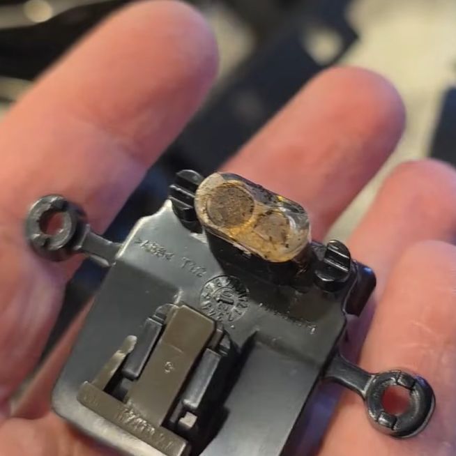
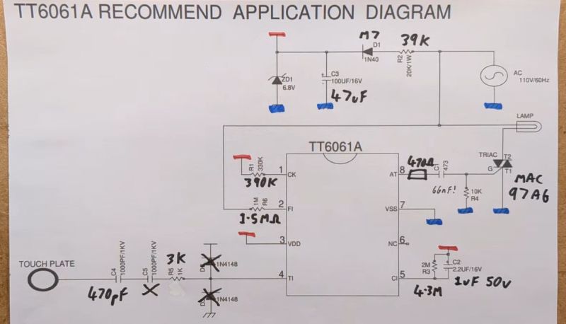
These unassuming little boxes are built around the Tontek TT6061A, listed as a ‘touch dimmer’, which uses a triac to control the output current. There are four levels, ranging from off to full brightness, before the next touch event turns the output off again.

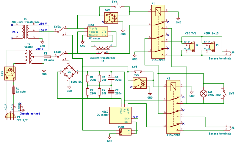
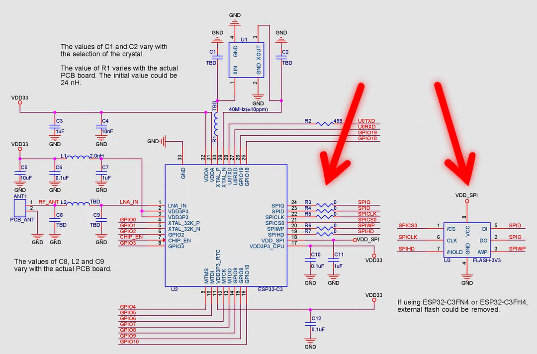
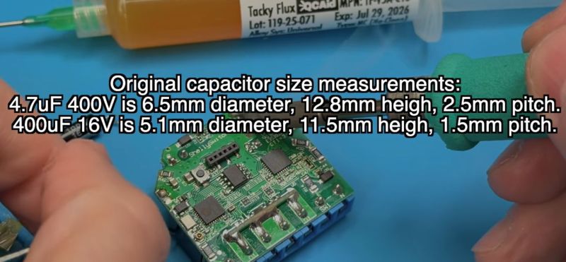
With the output off, [Clive] measured 0.7 W power usage. After popping open the plastic enclosure, the circuitry turned out to largely follow the recommended application circuit from the datasheet — as can be seen in the above screenshot — with apparently a few cost optimizations, in the form of omitted diodes and a capacitor.

The problem with these devices is that they are only really suitable for dimming low-power resistive loads like incandescent lights, with LED lights likely requiring the unpopulated capacitor spot on the PCB to be populated to tweak the chip’s triac timing, among other changes. There are also the slight issues with no real concern with them radiating EMI, and the exciting possibility of getting shocked at mains voltage without at least a class-Y capacitor installed.

Perhaps using a capacitive touch controller instead that works through plastic, for example, isn’t such a crazy alternative here, especially since they’re not really much more expensive and less likely to shock you. Want to create your own triac designs? We have just the post to get you started.

Isolated AC/DC Power Supply and Testing Station for 230 V Devices

When you’re testing or debugging some mains-powered gear, plugging it directly into the outlet can often be an exciting proposition. If such excitement is not really your thing, you can opt for an isolation transformer and other types of safeties. In the case of [Michał Słomkowski], he opted to take a few steps further by modding a vintage East-German isolating variac with a broken amp meter into an isolated AC/DC power supply and testing station.

The core is formed by the isolated variable transformer, to which a configurable DC output section, a current limiter and digital voltage and current read-outs were added. This enables a variable AC output of 0 – 330 VAC and 0 – 450 VDC on their respective terminals, with the incandescent light bulb providing an optional current limiter.

In its final configuration [Michał] has been using the device for the past four years now for a range of tasks, including the simulating of various undesirable mains power conditions, varying the speed of an old Soviet-era drill, powering vacuum tube devices, capacitor reforming and of course running 100-120 VAC devices from e.g. the US.

As far as feature set goes, we have to admit that it is an impressive device, indeed. Although some parts of it are clearly playing it fast and loose with best practices, with [Michał] admitting to not being an electrician, it was clearly engineered well enough to survive a few years of use, something which cannot be said for even professional laboratory equipment these days.

Polymer Skins That Change Color and Texture When Exposed to Water

Researchers at Stanford University recently came up with an interesting way (Phys.org summary) to create patterns and colors that emerge when a polymer is exposed to water. Although the paper itself is sadly paywalled with no preprint available, it’s fairly easily summarized and illustrated with details from the Supplementary Data section. The polymer used is poly(3,4-ethylenedioxythiophene) polystyrene sulfonate (PEDOT:PSS), which when exposed to an electron beam (electron-beam lithography) undergoes certain changes that become apparent when said water is added.

The polymer is hygroscopic, but the electron beam modifies the extent to which a specific area swells up, thus making it possible to create patterns that depend on the amount of electron beam exposure. In order to ‘colorize’ the polymer, complex cavities are created that modify the angular distribution of light, as illustrated in the top image from the Supplemental Data docx file.

By varying the concentration of IPA versus water, the intermediate swelling states can be controlled. Although this sounds pretty advanced, if you look at the supplementary videos that are already sped up a lot, you can see that it is a very slow process. Compared to an octopus and kin whose ability to alter their own skin texture and coloring is legendary and directly controlled by their nervous system, this isn’t quite in the same ballpark yet, even if it’s pretty cool to watch.

Vacuum Fluorescent Displays Explained

After having been sent a vacuum fluorescent display (VFD) based clock for a review, [Anthony Francis-Jones] took the opportunity to explain how these types of displays work.

Although VFDs are generally praised for their very pleasant appearance, they’re also relatively low-power compared to the similar cathode ray tubes. The tungsten wire cathode with its oxide coating produces the electrons whenever the relatively low supply voltage is applied, with a positively charged grid between it and the phosphors on the anode side inducing the accelerating force.

Although a few different digit control configurations exist, all VFDs follow this basic layout. The reason why they’re also called ‘cold cathode’ displays is because the cathode doesn’t heat up nearly as hot as those of a typical vacuum tube, at a mere 650 °C. Since this temperature is confined to the very fine cathode mesh, this is not noticeable outside of the glass envelope.

While LCDs and OLED displays have basically eradicated the VFD market, these phosphor-based displays still readily beat out LCDs when it comes to viewing angles, lack of polarization filter, brightness and low temperature performance, as LC displays become extremely sluggish in cold weather. Perhaps their biggest flaw is the need for a vacuum to work, inside very much breakable glass, as this is usually how VFDs die.

Converting a Nebra Cryptocurrency Miner To a Meshcore Repeater

After the swivel by Helium Inc. towards simply running distributed WiFi hotspots after for years pushing LoRaWAN nodes, much of the associated hardware became effectively obsolete. This led to quite a few of these Nebra LoRa Miners getting sold off, with the [Buy it Fix it] channel being one of those who sought to give these chunks of IP-67-rated computing hardware a new life.

Originally designed to be part of the Helium Network Token (HNT) cryptocurrency mining operation, with users getting rewarded by having these devices operating, they contain fairly off-the-shelf hardware. As can be glanced from e.g. the Sparkfun product page, it’s basically a Raspberry Pi Compute Module 3+ on a breakout board with a RAK 2287 LoRa module. The idea in the video was to convert it into a Meshcore repeater, which ought to be fairly straightforward, one might think.

Unfortunately the unit came with a dead eMMC chip on the compute module, the LoRa module wasn’t compatible with Meshcore, and the Nebra breakout board only covers the first 24 pins of the standard RPi header on its pin header.

The solutions involved using a µSD card for the firmware instead of the eMMC, and doing some creative routing on the bottom of the breakout board to connect the unconnected pins on the breakout’s RPi header to the pins on the compute module’s connector. This way a compatible LoRa module could be placed on this header.

Rather than buying an off-the-shelf LoRa module for the RPi and waiting for delivery, a custom module was assembled from an eByte E22 LoRa module and some stripboard to test whether the contraption would work at all. Fortunately a test of the system as a Meshcore repeater showed that it works as intended, serving as a pretty decent proof-of-concept of how to repurpose those systems from a defunct crypto mining scheme into a typical LoRa repeater, whether Meshcore or equivalent.

PlayStation 3 Emulator RPCS3 Can Play Nearly Three-Quarters of All PS3 Games

Although already having entered the territory of ‘retro gaming’, the Sony PlayStation 3 remains a notoriously hard to emulate game console. Much of this is to blame on its unique PowerPC-based Cell processor architecture, which uses a highly parallel approach across its asymmetric multi-core die that is very hard to map to more standard architectures like those in today’s x86 and ARM CPUs. This makes it even more amazing that the RPCS3 emulator team has now crossed the 70% ‘playable’ threshold on their compatibility list.

This doesn’t mean that you can fire up these games on any purported ‘gaming system’, as the system requirements are pretty steep. If you want any kind of enjoyable performance the recommended PC specifications feature an Intel 10th generation 6-core CPU, 16 GB of dual-channel RAM and a NVIDIA RTX 2000 or AMD RX 5000 series GPU or better.

It should be noted here also that the ‘playable’ tag in the compatibility list means that the game can be completed without game breaking glitches. Performance remains an issue, with very creative optimizations through e.g. the abuse of x86 SIMD instructions remaining the topic of research by the emulator developers. Yet as original PS3 hardware gradually becomes less available, the importance of projects like RPCS3 will become more clear.


Header: Evan-Amos, Public domain.

Repair and Reverse-Engineering of Nespresso Vertuo Next Coffee Machines

Well there’s your problem. (Credit: Mark Funeaux, YouTube)

Akin to the razor-and-blades model, capsule-based coffee machines are an endless grind of overpriced pods and cheaply made machines that you’re supposed to throw out and buy a new one of, just so that you don’t waste all the proprietary pods you still have at home. What this also means is a seemingly endless supply of free broken capsule coffee makers that might be repairable. This is roughly how [Mark Furneaux] got into the habit of obtaining various Nespresso VertuoLine machines for attempted repairs.

The VirtuoLine machines feature the capsule with a bar code printed on the bottom of the lip, requiring the capsule to be spun around so that it can be read by the optical reader. Upon successful reading, the code is passed to the MCU after which the brewing process is either commenced or cruelly halted if the code fails. Two of the Vertuo Next machines that [Mark] got had such capsule reading errors, leading to a full teardown of the first after the scanner board turned out to work fine.

Long story short and many hours of scrubbed footage later, one machine was apparently missing the lens assembly on top of the photo diode and IR LED, while the other simply had these lenses gunked up with spilled coffee. Of course, getting to this lens assembly still required a full machine teardown, making cleaning it an arduous task.

Unfortunately the machine that had the missing lens assembly turned out to have another fault which even after hours of debugging remained elusive, but at least there was one working coffee machine afterwards to make a cup of joe to make [Mark] feel slightly better about his life choices. As for why the lens assembly was missing, it’s quite possible that someone else tried to repair the original fault, didn’t find it, and reassembled the machine without the lens before passing the problem on to the next victim.

Espressif Introduces the ESP32-E22 Wi-Fi 6E and Bluetooth Co-Processor

Espressif has unveiled its latest major chip in the form of the ESP32-E22. Officially referred to as a Radio Co-Processor (RCP), it’s intended to be used via its PCIe 2.1 or SDIO 3.0 host interface to provide wireless communications to an SoC or similar.

This wireless functionality includes full WiFi 6E functionality across all three bands, 160 MHz channel bandwidth and 2×2 MU-MIMO, making it quite a leap from the basic WiFi provided by e.g. the ESP32-S* and -C* series. There is also Bluetooth Classic and BLE 5.4 support, which is a relief for those who were missing Bluetooth Classic in all but the original ESP32 for e.g. A2DP sinks and sources.

The ESP32-E22 processing grunt is provided by two proprietary Espressif RISC-V CPU cores that can run at 500 MHz. At this point no details appear to be available about whether a low-power core is also present, nor any additional peripherals. Since the graphics on the Espressif PR article appear to be generic, machine-generated images – that switch the chip’s appearance from a BGA to an LQFP package at random – there’s little more that we can gather from there either.

Currently Espressif is making engineering samples available to interested parties after presumed vetting, which would indicate that any kind of public release will still be a while off. Whether this chip would make for an interesting stand-alone MCU or SoC along the lines of the -S3 or -P4 will remain a bit of a mystery for a bit longer.

Thanks to [Rogan] for the tip.

How to use Tiny Open Loop Actuators for a Living Mirror

How do you go about making a mirror with 128 segments, each of which can be independently angled? That was the question that a certain bloke over at [Time Sink Studio] found himself pondering on, to ultimately settle on a whole batch of mini-actuators bought through AliExpress. These stepper-based actuators appear to be akin to those used with certain Oppo smartphones with pop-up camera, costing less than half a dollar for a very compact and quite fast actuator.

The basic design is very much akin to a macro version of a micromirror device, as used in e.g. DLP projectors, which rely on a kinetic mirror mount to enable precise alignment. With the small actuators travelling up to 8 mm each, the mirrors can cover 73 mm at a distance of 4 meters from a wall.

With the required angle of the mirror being effectively just the application of the Pythagorean theorem, the biggest challenge was probably calibrating these linear motors. Since they’re open loop devices, they are zeroed much like the steppers on 3D printers, by finding the end limit and counting steps from that known point. This doesn’t make drift impossible, but for projecting light onto walls it’s clearly more than good enough.

SoundSlab: How to Make a Synthesizer With All the Button Screens

Although arguably redundant on a typical computer keyboard, the idea of embedding small screens into the buttons on devices like audio production gear that often have so many buttons can make a lot of sense. As exemplified by devices with a UX that regularly degrades into scrolling through options on a tiny screen. This was basically the impetus for [Craig J Bishop] a few years ago to set out on a design project called the SoundSlab audio sequencer/sampler/synthesizer and slab that would make those buttons much more functional.

Obviously, the right way to start the project is to bulk buy hundreds of 0.85″ 128×128 LCDs so that you’re firmly locked into that choice. Fortunately, it turned out that the most annoying part of this LCD was the non-standard 0.7 mm pitch on its flat flex cable (FFC). This was worked around with an PCB adapter milled out of some copper-clad FR-1, which gave it a convenient PMOD interface for straightforward hook-up to a Xilinx Artix-7 FPGA board.

The buttons themselves were designed as 3D printed key caps for the LCDs that clipped onto typical Cherry MX-style mechanical keys. This also revealed that the original FFCs were too short, so they had to be replaced with new FFCs, that also adapted it to a standard 0.5 mm pitch. With this a 4×4 button prototype board could be constructed for testing.

Since that prototype [Craig] has built a full-sized SoundSlab grid, with a custom FPGA board and HDMI input, of which a preview can be seen in the post, along with a promise by [Craig] to soon post the rest of the SoundSlab development.

Thanks to [JohnS_AZ] for the tip.

Washington State Bill Seeks to Add Firearms Detection to 3D Printers

Washington State’s House Bill 2321 is currently causing a bit of an uproar, as it seeks to add blocking technologies to 3D printers, in order to prevent them from printing “a firearm or illegal firearm parts”, as per the full text. Sponsored by a sizeable number of House members, it’s currently in committee, so the likelihood of it being put to a floor vote in the House is still remote, never mind it passing the Senate. Regardless, it is another chapter in the story of homemade firearms, which increasingly focuses on private 3D printers.

Also called ‘ghost guns‘ in the US, these can be assembled from spare parts, from kits, from home-made components, or a combination of these. While the most important parts of a firearm, like the barrel, have to be made out of something like metal, the rest can feature significant amounts of plastic parts, though the exact amount varies wildly among current 3D-printed weapons.

Since legally the receiver and frame are considered to be ‘firearms’, these are the focus of this proposed bill, which covers both additive and subtractive technology. The proposal is that a special firearms detection algorithm has to give the okay for the design files to be passed on to the machine.

This blocking feature would have to be standard for all machines sold or transferred in the state, with a special ‘preprint authentication’ handshake protocol required. The attorney general is here expected to create and maintain a database of the no longer legal firearm and parts designs for those without a requisite license.

Putting aside for a moment the ridiculousness of implementing such a scanning feature, even if it wouldn’t be child’s play to circumvent, it also barks up the wrong tree. Although in the most recent ruling pertaining to this topic in Bondi v. VanDerStok it was acknowledged that advances in 3D printing have made this worth considering from a legislative context, the main issue with ‘ghost guns’ comes still by far from kits and similar sources.

Based on this, it seems highly unlikely that HB 2321 will be put up for a vote, never mind get signed into law. Although 3D printed designs like the 9 mm x1 9 mm cartridge Urutau bullpup are apparently quite functional, it’s notable that its manufacturing involves many steps, many DIY store parts, and a bolt carrier manufactured from steel bar stock, not to mention a significant time investment. Trying to detect ‘firearm parts’ at any of these steps would seem to be a fool’s errand, even if privacy considerations were not an issue.

What to do With a Flash-less ESP32-C3 Super Mini Board?

In an update video by [Hacker University] to an earlier video on ESP32-C3 Super Mini development boards that feature a Flash-less version of this MCU, the question of adding your own Flash IC to these boards is addressed. The short version is that while it is possible, it’s definitely not going to be easy, as pins including SPIHD (19) and SPICLK (22) and SPIQ (24) are not broken out on the board and thus require one to directly solder wires to the QFN pads.

Considering how sketchy it would be to have multiple wires running off to an external Flash IC, this raises many questions about the feasibility, as well as cost-effectiveness. Some in the comments to the video remark that instead you may as well swap the MCU with a version that does contain built-in Flash, but this is countered with the argument that a new ESP32-C3 Super Mini board with the right MCU costs as much as a loose MCU from your favorite purveyor of ICs.

Ultimately this lends some credence to calling these zero Flash Super Mini boards a ‘scam’, as their use cases would seem to be extremely limited and their Flash-less nature very poorly advertised.

ESP32-c3 reference implementation with external flash. (Credit: Espressif)
ESP32-C3 reference implementation with external flash. (Credit: Espressif)

Beating the World Record for Fastest Flying Drone Once Again

The fun part about world records is that anyone can take a swing at breaking them, which is what [Luke Maximo Bell] has been doing with the drone speed record for the past years, along with other teams in a friendly competition. After having some Aussie blokes previously smash the record with a blistering 626 km/h, the challenge was on for [Luke] and his dad to reclaim the title. This they did with the V4 of their quadcopter design, adding a range of improvements including new engines, new props and an optimized body to eek out more performance.

In the video we see these changes and the tests in detail. Interestingly, the simulations ran on the computer showed that the new body actually had to be larger, necessitating the use of a larger FDM printer. Fortunately a certain FDM 3D printer company sponsors just about everyone out there, hence the new design was printed on a Bambu Lab H2D, also making use of the dual extruder feature to print combined PETG/TPU parts.

It was also attempted to have a follow camera attached to a second FPV done in the form of a 360 degrees camera, but this turned out to be a bit too complex to get good shots, so this will have to be retried again.

In the end a new world record was set at an average of 657 km/h, which sets the stage for the next team to try and overtake it again. As for where the limit is, propeller airplanes have hit over 800 km/h,  so there’s still quite a way to go before details like the sound barrier become a problem.

The Shelly 2.5 Smart Relay Design Flaw Killing Capacitors

Part of any self-respecting Smart Home, smart relays are useful for switching and monitoring loads that do not plug into an outlet. This also makes them a lot more integrated, and thus, a long lifespan is very welcome. Unfortunately, the popular Shelly 2.5 smart relays seem to be having a bit of a design flaw as they’re dying in droves once their 2-year warranty period is up. The cause and repair are covered in a recent [VoltLog] video on YouTube.

As noted in the Shelly documentation for the device, it’s a very compact form factor device, with screw terminals, two relays, and three fairly large electrolytic capacitors sharing very little space with the rest of the components. The apparent flaw comes in the form of these capacitors failing, with the video showing that one 100 µF capacitor has a massively increased ESR, likely due to electrolyte venting. This results in the observed symptoms, such as WiFi connectivity issues and audible hissing, the latter of which is demonstrated in the video.

Due to the cramped space, the replacement capacitors need to be at least as small as listed in the video and in the top screenshot, though mind the typo as ‘400µF’ has to be ‘100µF’. This limitation posed a bit of a problem, as for the two 400V, 4.7 µF capacitors, there aren’t that many options in that form factor. The original capacitors are definitely B- or C-grade ones, with the two large capacitors Chongx branded, being a well-known budget capacitor brand. The other capacitor’s branding cannot be made out in the video, but is likely also Chongx or a similar, less well-regarded Chinese brand.

For the replacements, a Nippon Chemicon capacitor was picked for the 100 µF capacitor, and Ymin-branded capacitors to fit within the size limitations. Picking Ymin over a second Nippon Chemicon set or similar was due to these unfortunate sizing limitations, but these Ymin replacement capacitors had the best datasheet of the options on LCSC. All of these capacitors have to be rated for 105°C, for obvious reasons.

Although it’s not easy to say for certain what caused these capacitors to fail so quickly without more data, it seems likely that having the SMPS circuitry for the 3.3V rail bunched up cozily with the three electrolytic capacitors and what looks like two load resistors inside the cramped enclosure with no clear ventilation holes does little to help the electrolytic capacitors hit their listed MTBF hours. Hopefully, using the new capacitors, these relays will last longer than 2-3 years before another recapping is needed.

The Journey of Finding the Right Press Brake

Press brakes are invaluable tools when working with sheet metal, but along with their almost infinite versatility comes a dizzying number of press brake types. After starting with an old-school, purely mechanical press brake, [Wes] of Watch Wes Work fame had been thinking of upgrading said press brake to a hydraulic configuration, but soured on this after facing all the disadvantages of the chosen approach. Thus, one does what any rational person does and purchases a used and very much untested 45-ton computer-controlled hydraulic press brake.

The video first explores the pros and cons of the various types of press brakes, with the issue of providing a balanced force across the entirety of the press brake’s dies being the largest problem. Although various mechanical and hydraulic solutions were attempted over the decades, a computer-controlled press brake like this Gasparini PBS 045 that [Wes] got is probably one of the more effective solutions, even if it provides the headache of more electrical and electronic things that can go wrong. The above screenshot of its basic workings should make that quite obvious, along with [Wes]’s detailed explanation.

As it turned out, this about 25-year-old Italian press brake wasn’t in such a terrible nick, but needed some badly needed TLC and obligatory breaker testing to bring it back to life. While it doesn’t like you not centering the part, this can be worked around by specifying that the part is actually larger than it is. Although [Wes] got it working well enough to do some work with it, it still has some gremlins left in it that will hopefully be hunted down over the coming time and video(s).

The Best Robot Mop System: Flat, Spinning, or Roller?

When it comes to designing a mopping robot, there are a number of approaches you can pick from, including just having the movement of the robot push the soggy mop over the floor, having spinning pads, or even a big spinning roller. But what difference does it make? Recently the [Vacuum Wars] channel ran a comparison to find out the answer.

The two spinning pad design is interesting, because it allows for the bot to move closer to objects or walls, and the base station doesn’t need the active scrubber that the simple static pad requires. The weakness of both types of flat mop design is that they are quickly saturated with dirt and moisture, after which they’ll happily smear it over the floor.

The spinning roller is the most complex, with the robot having its own onboard water tank, and a way to extract the dirty water from the mop and store it for disposal in the base station. Theoretically this would be the clear winner, with basically all of them having features like avoiding carpet.

Taking the test data from 150 different mopping robots that were made to clean up dried-up coffee stains, the results weren’t as clear-cut as one might perhaps expect due to the very limited scope of the test. But the comments to the video are perhaps more revealing. After all, most people don’t briefly run their robot mop over a few dried-up stains, but are faced with more severe real-life scenarios.

One commentator mentions their dogs dragging in a lot of mud on rainy days, in which case the spinning pads robot would end up spreading a thin film of mud across the floor. After upgrading to a spinning roller version this issue was resolved, though it’s readily admitted to be the more expensive system, with a much larger base station.

When in the video you see the details of what each approach involves on the side of the robot, the base station and the human caretaker, trade-offs are clear. Having the fixed flat pad is simple, but moves all complexity to the base station, with the spinning pads removing at least the need to motorize the base station. If you have small children or pets with muddy paws around, neither option works well, so you either have to whip out the human-powered mop or shell out for the high-end robotic solution.

Of course, you can also build your own super-charged robot mop, or a very thorough one, but definitely avoid mopping robots that are too cheap to actually work.

The eMac: Using Apple’s Forgotten Educational Mac in 2026

Beauty truly is in the eye of the beholder. (Credit: MattKC, YouTube)

What’s it like to use a 2002-era Apple eMac all-in-one in 2025? That’s what [MattKC] asked himself after obtaining one of these systems from a seller who ominously mentioned that it had been ‘left outside for years’.

The Apple iMac is a bit of a cult symbol, whether you’re talking about the iconic fruity iMac G3 or the desk lamp-like iMac G4, but few reminisce or actively collect the Apple eMac. Manufactured from 2002 to 2006, it featured the PowerPC 7450 (G4e) CPU with clock speeds ranging from 700 MHz to 1.42 GHz, as well as a 17″ CRT. In terms of design it was basically a bland iMac G3 that was firmly targeting the education markets to try and regain market share after Windows PCs had begun to eat its lunch there.

As for the model that [MattKC] purchased, it was this earliest model, featuring a 700 MHz PowerPC G4 CPU in addition to 640 MB SDRAM. Despite the seller’s description it seems to be in good nick with it firing right up, and even a glance inside after beating the challenge of 2.5 mm hex screws showed it to be in relatively good condition.

Unlike the iMac G3, you can play the Mac port of Halo on it, but the Minecraft port is very much not performant. With generally multimedia and gaming working well, it does show why the eMac was released, as it’s quite capable relative to an iMac G3 which would have struggled with the educational software of the era. We definitely hope that [MattKC] restores it to its full glory instead of ripping out its innards, as the neglected status of the eMac makes it much more likely to go extinct than PowerPC-based iMacs.

How Accurate is a 125 Year Old Resistance Standard?

Internals of the 1900 Evershed & Vignoles Ltd 1 ohm resistance standard. (Credit: Three-phase, YouTube)

Resistance standards are incredibly useful, but like so many precision references they require regular calibration, maintenance and certification to ensure that they stay within their datasheet tolerances. This raises the question of how well a resistance standard from the year 1900 performs after 125 years, without the benefits of modern modern engineering and standards. Cue the [Three-phase] YouTube channel testing a genuine Evershed & Vignoles Ltd one ohm resistance standard from 1900.

With mahogany construction and brass contacts it sure looks stylish, though the unit was missing the shorting pin that goes in between the two sides. This was a common feature of e.g. resistance decade boxes of the era, where you inserted pins to connect resistors until you hit the desired total. Inside the one ohm standard is a platinoid resistor, which is an alloy of copper, nickel, tungsten, and zinc. Based on the broad arrow mark on the bottom this unit was apparently owned by the UK’s Ordnance Board, which was part of what was then called the War Office.

After a quick gander at the internals, the standard was hooked up to a Keithley DMM7510 digital bench meter. The resistance standard’s ‘datasheet’ is listed on top of the unit on the brass plaques, including the effect of temperature on its accuracy. Adjusting for this, the measured ~1.016 Ω was within 1.6% tolerance, with as sidenote that this was with the unit not having been cleaned or otherwise having had maintenance performed on it since it was last used in service. Definitely not a bad feat.

Testing a Continuous Printing Mod for the Bambu Lab A1 Mini

There are a few types of continuous 3D printing with FDM printers, with a conveyer belt and automatic build plate swapping the most common types. The advantage of build plate swapping is that it automates the bit where normally a human would have to come in to remove finished parts from the build plate. A recent entry here is the Chitu PlateCycler C1M which the [Aurora Tech] YouTube channel had over for a review. This kit bolts onto the Bambu Lab A1 Mini FDM printer and comes with four extra PEI build plates for a not unreasonable $79 (€69).

As also noted in the review video, this is effectively a clone of the original swapmod A1m kit, but a big difference is that the Chitu kit comes with all of the parts and doesn’t require you to print anything yourself.

The different plates are prepared using a special tool that inserts G-code between the plate changes. Moving the bed in a specific way triggers the switch that lifts the finished plate off the magnetic bed by the plastic grip on the plate and loads a fresh plate from the stack. Here it was found that a small tolerance issue prevented the last plate from being used, but some sandpaper fixed this. Other than that it was a fairly painless experience, and for e.g. multi-color prints with separated colors – as demonstrated – it would seem to be a great way to churn out the entire model without manual intervention or a lot of wasted filament.

Perhaps the main issue that is central to all of these build plate swap mods is where the plates go after they’re pulled off the magnetic bed: the padded box is a great idea for the first one or two plates, but after that you get your PEI build plates with parts on them crashing on top of each other.

This is where perhaps something like a passive roller conveyer system could provide a nice gentle off-ramp, though this too would increase the footprint of the system. Regardless, the overall system seems to work well enough, allowing one to stack fresh plates in the chute and if you turn on build plate detection in the A1 you can even prevent the printer from trying to print on the magnetic bed.

Battle Born LFP Battery Melts With New Problem

Following up on user-reported cases of Battle Born LiFePO4 batteries displaying very hot positive terminals, [Will Prowse] decided to buy a brand new one of these LFP batteries for some controlled cycle testing.

Starting with 30 cycles with a charging current of 49 A and a discharge current of 99 A, this put it well within the 100 A continuous rating for the battery. There is also a surge current rating of 200 A for thirty seconds, but that was not tested here.

What’s interesting about the results here is that instead of the positive terminal getting visibly discolored as with the previous cases that we reported on, [Will] saw severe thermal effects on the side of the negative terminal to the point where the plastic enclosure was deforming due to severe internal heating.

During testing, the first two charge-discharge cycles showed full capacity, but after that the measured capacity became extremely erratic until the battery kept disconnecting randomly. After letting the battery cool down and trying again with 80 A discharge current the negative terminal side of the enclosure began to melt, which was a good hint to stop testing. After this the battery also couldn’t be charged any more by [Will]’s equipment, probably due to the sketchy contact inside the battery.

It’s clear that the plastic spacer inside the terminal bus bar was once again the primary cause, starting a cascade which resulted in not only the enclosure beginning to char and melt, but with heat damage visible throughout the battery. Considering that the battery was used as specified, without pushing its limits, it seems clear that nobody should be using these batteries for anything until Battle Born fixes what appears to be the sketchiest terminal and bus bar design ever seen in a high-current battery.

❌