Attributed to Picasso was the notion that when art critics get together they talk about content, style, trend, and meaning; but that when painters get together they talk about where to get the best turpentine. We can extend that sentiment into the digital age by saying that when philosophers get together they talk about ideas, theory, and meaning; but when hackers get together they talk about where to get the best tweezers.
In this video [nanofix] runs us through his collection of tweezers talking about what he likes and doesn’t like for each. If you’re just getting into microsoldering this video will have some tips about where you should start, and if you’ve been soldering tiny stuff for a while you might find some ideas for a helpful new bit of kit, or two.
If you’re interested in tweezers and novel applications you might want to check out “smart” tweezers, which can read capacitance and resistance values on the fly. Or read about a suction based SMD tool, which can securely hold SMD components with less risk of them flying across the bench and disappearing forever into the carpet on the floor.
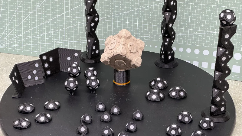
3D scanners rely on being able to identify physical features of an object, and line up what it saw a moment ago with what it sees now in order to build a 3D model. However, not every object is as distinct and visible as others at all angles, particularly in IR. One solution is reflective scanning markers, which are either pre-printed on a mat, or available as stickers that can be applied to objects to give the scanner a bit more to latch onto, visually speaking.
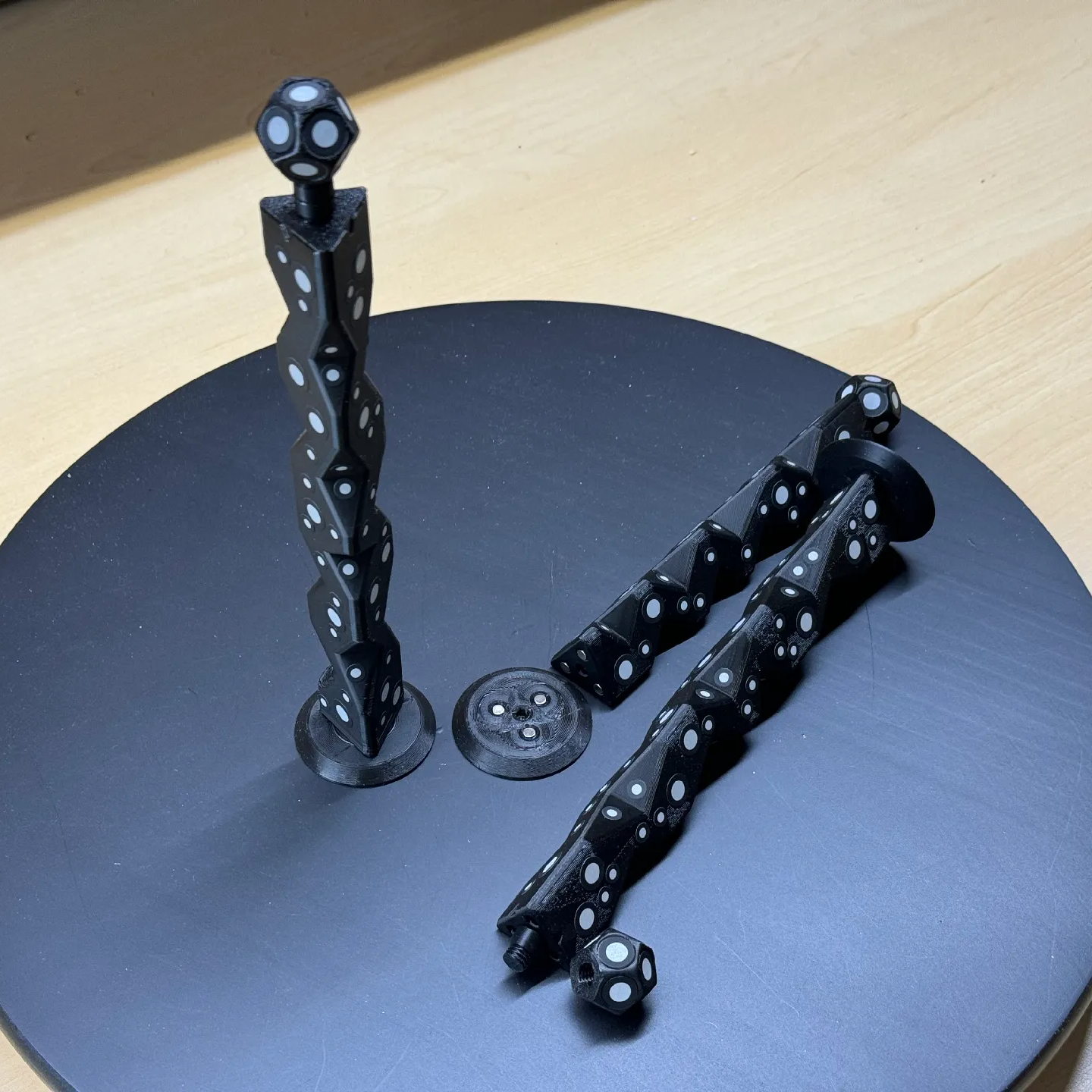
Magnetic mounts allow mixing and matching, as well as attaching directly to some objects to be scanned.
The main advantage (besides not having to remove stickers from the object afterwards) is that these printed markers present the reflective dots at a variety of angles during the scanning process. This makes the scene less sensitive to scanner angle in general, which is good because the angle at which to scan an important feature of an object is not always the angle that responds best.
By giving the scene more structure, the scanner can have a better shot at scanning reliably even if the reflectors aren’t on the target object itself. It also helps by making it easier to combine multiple scans. The more physical features scans have in common, the easier it is to align them.
Just to be clear, using these means one will, in effect, be 3D scanning the markers along with the target object. But once all the post-processing is done, one simply edits the model to remove everything except the target object.
[firstgizmo]’s DIY magnetic 3D scanning markers are an expanded take on an idea first presented by [Payo], who demonstrates the whole concept wonderfully in the video below.
3D scanning can be tremendously handy but it does have its quirks and limitations, and a tool like this can be the difference between a terrible scan and a serviceable one. For a quick catch-up on 3D scanning and its strengths and limitations, read our hands-on tour of using an all-in-one 3D scanner.
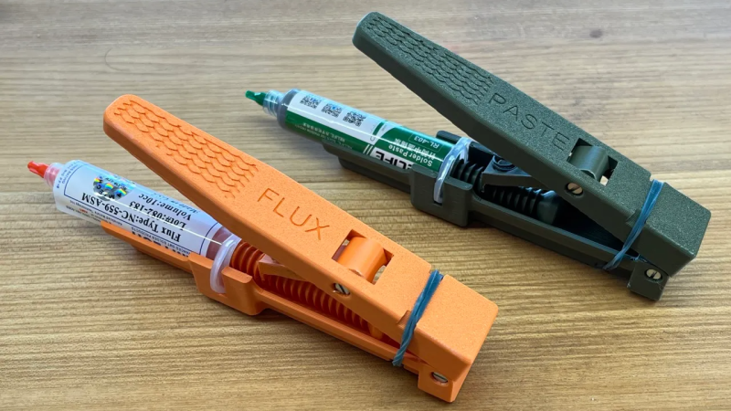
Syringes are pretty ergonomic, but when manually dispensing flux and solder paste it doesn’t take long before one wants a better way. [Elektroarzt]’s flux and solder paste dispenser design uses 3D-printed parts and minimal hardware (mostly M3x20 screws, and an optional spring) to improve handling and control.
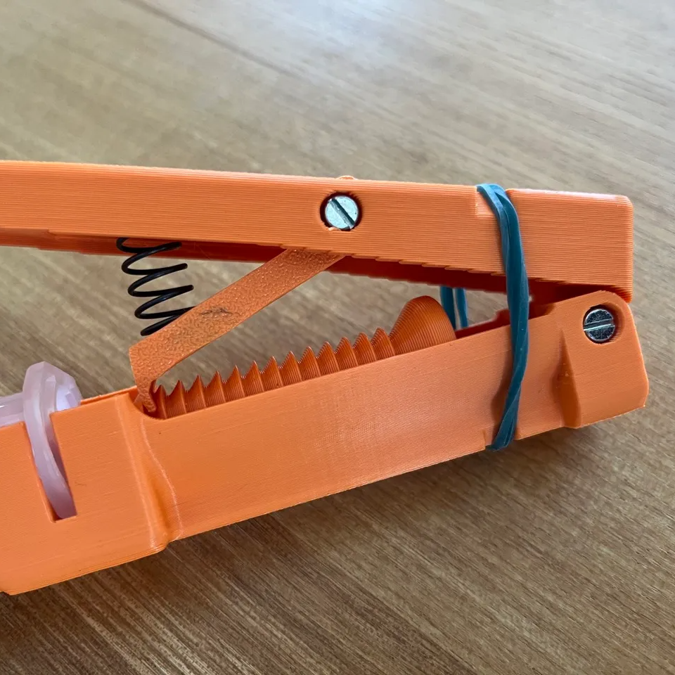
The operating principle is very similar to how a hot glue gun feeds a stick of glue.
How does it work? The ratcheting lever mechanism is similar to that of a hot glue gun, where an arm slips into notches in a rod when pressed down, driving it forward and never backward. In the process, a larger lever movement is translated into a shorter plunger travel, enhancing control.
The types of syringes this tool is meant to be used with have a plunger tip or piston (the rubber stopper-looking part, in contact with the liquid) inside the loaded syringe, but no plunger shaft attached to it. This is common with syringes meant to be loaded into tools or machines, and [Elektroarzt]’s tool can be used with any such syringe in a 10 cc size.
It’s an attractive design, and we like the way syringes top-load as well as the way the tool is made to lay flat on a tabletop, with the lever pointed up.
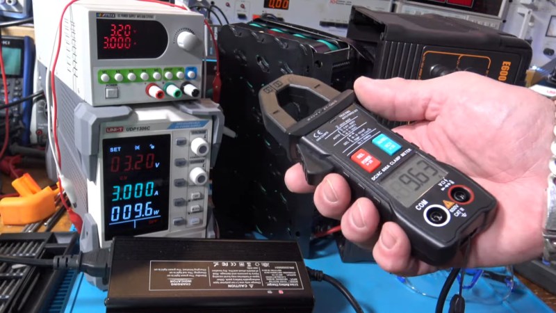
If you’re putting together an electronics lab from scratch you absolutely must get a multimeter to start. A typical multimeter will be able to do current measurements but it will require you to break the circuit you’re measuring and interface it to your meter using its mechanical probes.
A good choice for your second, or third, multimeter is a clamp-based one. Many of the clamp meters have the clamp probe available for current measurements while still allowing you to use the standard 4mm banana jack probes for other measurements, particularly voltage and resistance.
If you’re curious to know more about how clamp meters work the answer is that they rely on some physics called the Hall Effect, as explained by the good people at Fluke.
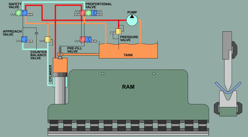
Press brakes are invaluable tools when working with sheet metal, but along with their almost infinite versatility comes a dizzying number of press brake types. After starting with an old-school, purely mechanical press brake, [Wes] of Watch Wes Work fame had been thinking of upgrading said press brake to a hydraulic configuration, but soured on this after facing all the disadvantages of the chosen approach. Thus, one does what any rational person does and purchases a used and very much untested 45-ton computer-controlled hydraulic press brake.
The video first explores the pros and cons of the various types of press brakes, with the issue of providing a balanced force across the entirety of the press brake’s dies being the largest problem. Although various mechanical and hydraulic solutions were attempted over the decades, a computer-controlled press brake like this Gasparini PBS 045 that [Wes] got is probably one of the more effective solutions, even if it provides the headache of more electrical and electronic things that can go wrong. The above screenshot of its basic workings should make that quite obvious, along with [Wes]’s detailed explanation.
As it turned out, this about 25-year-old Italian press brake wasn’t in such a terrible nick, but needed some badly needed TLC and obligatory breaker testing to bring it back to life. While it doesn’t like you not centering the part, this can be worked around by specifying that the part is actually larger than it is. Although [Wes] got it working well enough to do some work with it, it still has some gremlins left in it that will hopefully be hunted down over the coming time and video(s).
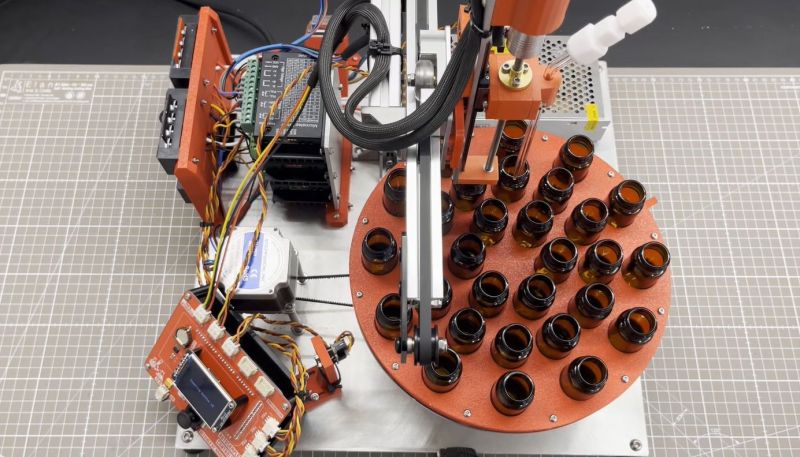
A common task in a laboratory setting is that of sampling, where a bit of e.g. liquid has to be sampled from a series of containers. Doing this by hand is possible, but tedious, ergo an autosampler can save a lot of time and tedium. Being not incredibly complex devices that have a lot in common with e.g. FDM 3D printers and CNC machines, it makes perfect sense to build one yourself, as [Markus Bindhammer] of Marb’s Lab on YouTube has done.
The specific design that [Markus] went for uses a sample carousel that can hold up to 30 bottles of 20 mL each. An ATmega-based board forms the brain of the machine, which can operate either independently or be controlled via I2C or serial. The axes and carousel are controlled by three stepper motors, each of which is driven by a TB6600 microstep driver.
Why this design is a time saver should be apparent, as you can load the carousel with bottles and have the autosampler handle the work over the course of however long the entire process takes instead of tying up a human. Initially the autosampler will be used for the synthesis of cadmium-selenium quantum dots, before it will be put to work for an HPLC/spectrometer project.
Although [Markus] intends this to be an open hardware and software project, it will take a bit longer to get all the files and documentation organized. Until then we will have to keep manually sampling, or use the video as the construction tutorial.
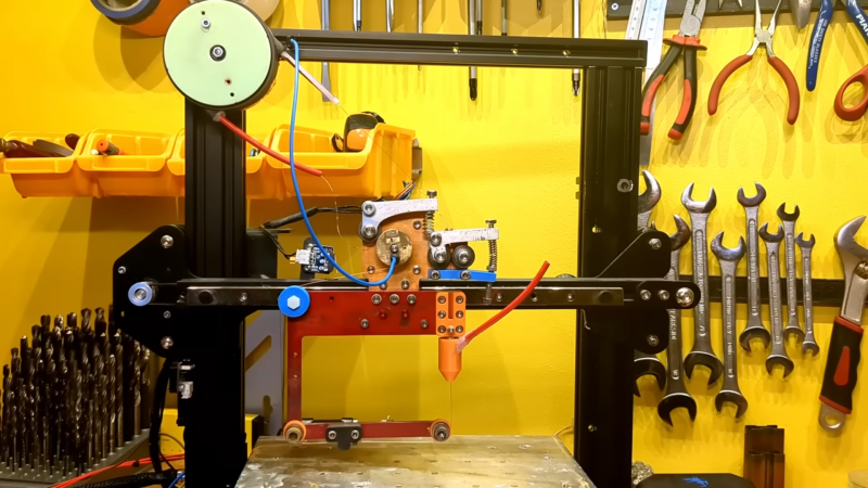
EDM (Electrical Discharge Machining) is one of those specialised manufacturing processes that are traditionally expensive and therefore somewhat underrepresented in the DIY and hacker scenes. It’s with great delight that we present EnderSpark, a solution to not one but two problems. The first problem is how to perform CNC operations on hard-to-machine materials such as hardened metals (without breaking the bank). The second problem is what to do with all those broken and forgotten previous-generation Creality Ender 3D printers we know you have stashed away.
To be honest, there isn’t much to a cheap 3D printer, and once you ditch the bed and extruder assembly, you aren’t left with a lot. Anyway, the first job was to add a 51:1 reduction gearbox between the NEMA 17 motors and the drive pullies, giving the much-needed boost to positional accuracy. Next, the X and Y axes were beefed up with a pair of inexpensive MGN12H linear rails to help them cope with the weight of the water bath.
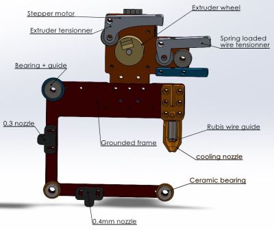
The majority of the work is in the wire feeder assembly, which was constructed around a custom-machined aluminium plate. It’s not lost on us how the original RepRap bootstrapping concept could be applied here: a basic frame made externally in a low-cost material, then using the machine to cut a much thicker, stronger copy for its own upgrade. The main guide nozzle is an off-the-shelf ruby part surrounded by a 3D printed water-cooling jacket. To maximise power transfer from the wire into the electrically conductive workpiece material, the top part of the wire feeder, including the wire itself, is one electrode, and the entire bottom part of the frame is electrically isolated from it. The bottom part pulls the ‘consumed’ stock wire through the nozzle above and keeps it under tension, sending it onward to the waste spool.
Electrically speaking, the project is based on stock Ender electronics, with an additional power driver stage to send capacitor-discharge-derived pulses down the wire from the 48V power supply, up to 10A, generating the needed tiny sparks as the wire is advanced into the electrically grounded workpiece. Industrial machines operate around twice this voltage, but safety is a big issue with a DIY machine. Not to mention 48V and water don’t make the best of friends. Speaking of water, it needs to be de-ionised to reduce dielectric loss, but ionic contamination will build up over time, so it needs to be regularly changed.
Software-wise, the machine is running on G-code, so all that is needed is a custom plugin for Fusion 360 to turn the extracted toolpath (they’re using the Wazer water cutter profile as a basis) into G-code, with knowledge of the material. There aren’t too many variables to play with there.
In the future, a few things are being considered. Adding closed-loop control of the pulse energy would be straightforward, but controlling the horizontal feed rate would be a little trickier to implement with a pure G-code approach. We’ll keep an eye on the project and report back any advances!
Hot glue guns are pretty simple beasts: there’s an on/off switch, a heating element, and a source of current, be it battery or wired. You turn it on, and the heater starts warming up; eventually you can start extruding the thermoplastic sticks we call “hot glue”. Since there’s no temperature control, the longer you run the gun, the warmer it gets until it is inevitably hotter than you actually want– either burning you or oozing thermoplastic out the tip. [Mellow_Labs] was sick of that after a marathon hot-glue session, and decided to improve on his hot glue gun with PID tuning in the video embedded below.
PID tuning is probably a familiar concept to most of you, particularly those who have 3D printers, where it’s used in exactly the same way [Mellow_Labs] puts it to work in the hot glue gun. By varying the input (in this case the power to the heater) proportional both to the Parameter (in this case, temperature) as well as the Integral and Derivative of that value, you can have a much steadier control than more naive algorithms, like the simple “on/off” thermostat that leads to large temperature swings.
In this case [Mellow_Labs] is implementing the PID control using a thermistor that looks like it came from a 3D printer, and a MOSFET driven by an RP2040. Microcontroller gets its power via the hot glue gun’s battery fed through a buck converter. Since he has them, a small OLED screen displays temperature, which is set with a pair of push-buttons. Thus, one can set a temperature hot enough to melt the glue, but low enough to avoid oozing or third degree burns.
He does not share the code he’s running on the RP2040, but if you are inspired to replicate this project and don’t want to roll your own, there are plenty of example PID scripts out there, like the one in this lovely robot. No, PID isn’t reserved for thermostats– but if you are controlling heat, it’s not reserved for electric, either. Some intrepid soul put built a PID controller for a charcoal BBQ once.
[Kerry Wong] points out that the Uni-T MSO oscilloscopes have a logic analyzer built in — that’s the MSO, or Mixed Signal Oscilloscope, part — but you have to add the probes. He shows you how it works in a recent video below.
He’s looked at the scope’s analog capabilities before and was not unimpressed. The probes aren’t inexpensive, but they do unlock the mixed signal capabilities of the instrument.
Although simple logic analyzers are very affordable today, having the capability integrated with your scope has several advantages, including integrated triggering and the simple convenience of being able to switch measurement modes with no problem.
In many cases, being able to do things like decode UART signals without dragging out a laptop and firing up software is a nice feature. If all you’ve used are the super-cheap USB logic analyzers, you may find some of the features of a more serious instrument surprising.
Is it worth the extra expense? That depends on you and what you are doing. But if you ever wondered if it was worth splurging on digital probes for a UNI-T scope, [Kerry] can help you decide.
Not that simple logic analyzers aren’t useful, and they certainly cost less. Some of them will even work as a scope, too.
![[nanofix] and his assortment of tweezers](https://hackaday.com/wp-content/uploads/2026/01/nanofix-tweezers-banner.jpg?w=800)

 It’s not lost on us how the original RepRap bootstrapping concept could be applied here: a basic frame made externally in a low-cost material, then using the machine to cut a much thicker, stronger copy for its own upgrade. The main guide nozzle is an off-the-shelf ruby part surrounded by a 3D printed water-cooling jacket. To maximise power transfer from the wire into the electrically conductive workpiece material, the top part of the wire feeder, including the wire itself, is one electrode, and the entire bottom part of the frame is electrically isolated from it. The bottom part pulls the ‘consumed’ stock wire through the nozzle above and keeps it under tension, sending it onward to the waste spool.