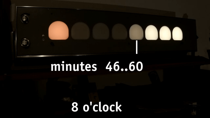
Creative clocks are a dime a dozen, even clocks that use binary have been created in nearly every format. [typo] promises a clever adaptation to the binary format, and it promises a more usable display. Using a combination of both traditional binary and digital gradients creates a usable and yet still nerdy fun clock.
[typo]’s clock fits the traditional binary counting method with the hours on the left side of its face. On the other hand, its right side presents a lighting gradient depending on the completion of the hour. While this is simple in principle, [typo] chose to correct what many don’t consider when deploying visual gradients. The human eye doesn’t see everything exactly as it is, which creates a rough logarithmic curve that gets corrected for in the binary/digital hybrid clock.
No matter the item on my list of childhood occupational dreams, one constant ran throughout: I saw myself using an old-fashioned punch clock with the longish time cards and everything. I now realize that I have some trouble with the daily transitions of life. In my childish wisdom, I somehow knew that doing this one thing would be enough to signify the beginning and end of work for the day, effectively putting me in the mood, and then pulling me back out of it.
But that day never came. Well, it sort of did this year. I realized a slightly newer dream of working at a thrift store, and they use something that I feel like I see everywhere now that I’ve left the place — a system called UKG that uses mag-stripe cards to handle punches. No it was not the same as a real punch clock, not that I have experience with a one. And now I just want to use one even more, to track my Hackaday work and other projects. At the moment, I’m torn between wanting to make one that uses mag-stripe cards or something, and just buying an old punch clock from eBay.
I keep calling it a ‘punch clock’, but it has a proper name, and that is the Bundy clock. I soon began to wonder how these things could both keep exact time mechanically, but also create a literal inked stamp of said time and date. I pictured a giant date stamper, not giant in all proportions, but generally larger than your average handheld one because of all the mechanisms that surely must be inside the Bundy clock. So, how do these things work? Let’s find out.
Bundy’s Wonder
Since the dawn of train transportation and the resulting surge of organized work during the industrial revolution, employers have had a need to track employees’ time. But it wasn’t until the late 1880s that timekeeping would become so automatic.
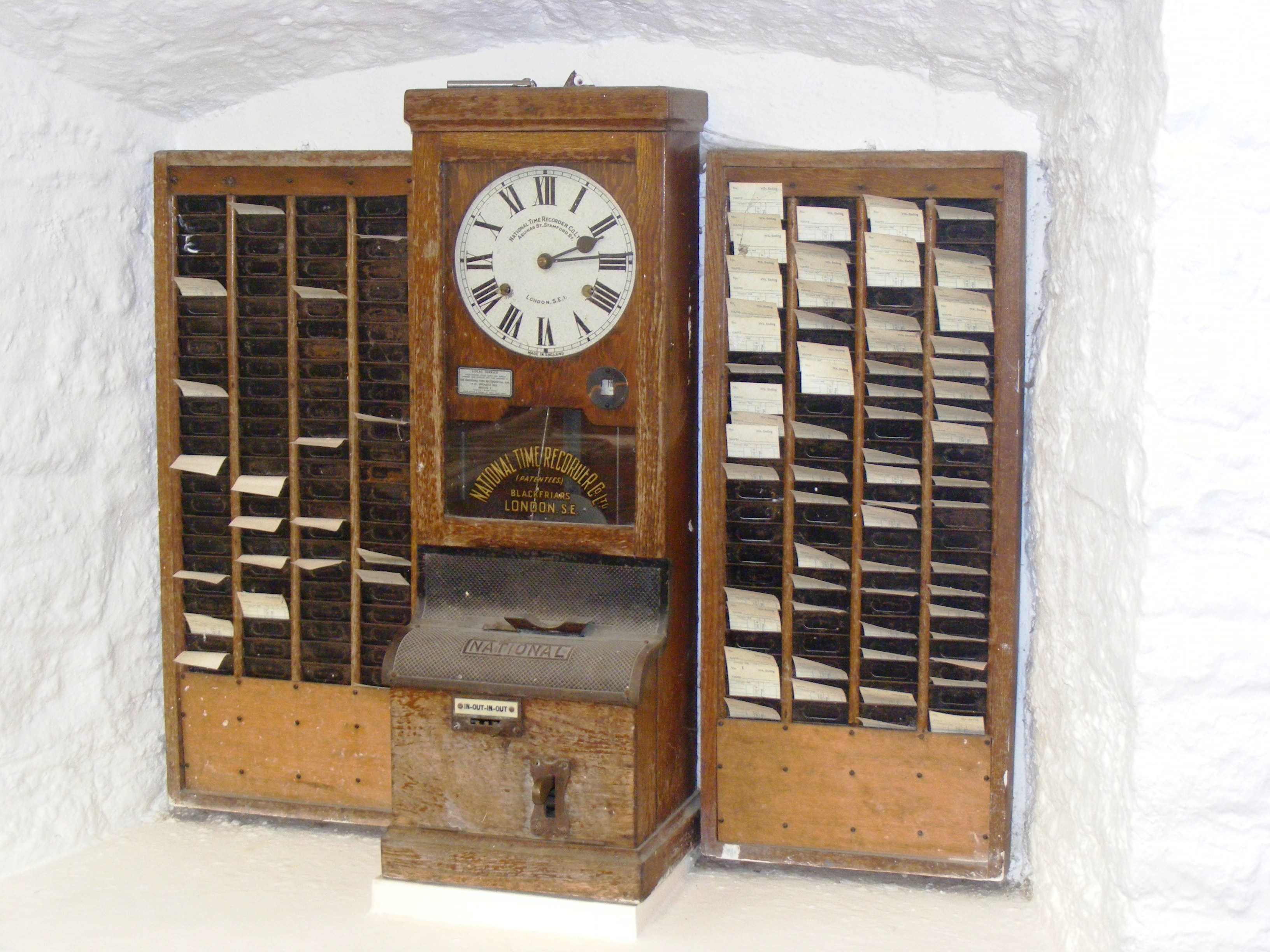
An early example of a Bundy clock that used cards, made by National Time Recorder Co. Ltd. Public domain via Wikipedia
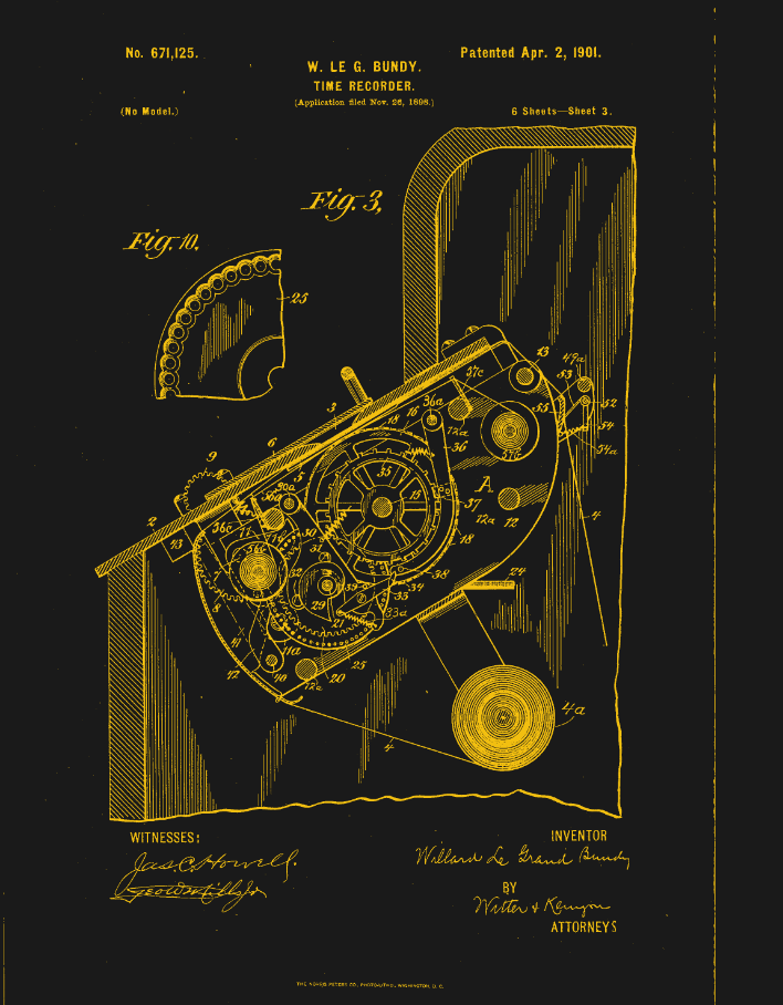
Willard Le Grand Bundy was a jeweler in Auburn, New York who invented a timekeeping clock in 1888. A few years later, Willard and his brother Harlow formed a company to mass-produce the clocks.
By the early 20th century, Bundy clocks were in use all over the world to monitor attendance. The Bundy Manufacturing Company grew and grew, and through a series of mergers, became part of what would become IBM. They sold the time-keeping business to Simplex in 1958.
Looking at Willard Le Grand Bundy’s original clock, which appears to be a few feet tall and demonstrates the inner workings quite beautifully through a series of glass panels, it’s no wonder that it is capable of time-stamping magic.
Part of that magic is evident in the video below. Workers file by the (more modern) time clock and operate as if on autopilot, grabbing their card from one set of pockets, inserting it willy-nilly into the machine, and then tucking it in safely on the other side until lunch. This is the part that fascinates me the most — the willy-nilly insertion part. How on Earth does the clock handle this? Let’s take a look.
Okay, first of all, you probably noticed that the video doesn’t mention Willard Le Grand Bundy at all, just some guy named Daniel M. Cooper. So what gives? Well, they both invented time-recording machines, and just a few years apart.
The main difference is that Bundy’s clock wasn’t designed around cards, but around keys. Employees carried around a metal key with a number stamped on it. When it was time clock in or out, they inserted the key, and the machine stamped the time and the key number on a paper roll. Cooper’s machine was designed around cards, which I’ll discuss next. Although the operation of Bundy’s machine fell out of fashion, the name had stuck, and Bundy clocks evolved slightly to use cards.
Plotting Time
You would maybe think of time cards as important to the scheme, but a bit of an afterthought compared with the clock itself. That’s not at all the case with Cooper’s “Bundy”. It was designed around the card, which is a fixed size and has rows and columns corresponding to days of the week, with room for four punches per day.
Essentially, the card is mechanically indexed inside the machine. When the card is inserted in the top slot, it gets pulled straight down by gravity, and goes until it hits a fixed metal stop that defines vertical zero. No matter how haphazardly you insert the card, the Bundy clock takes card of things. Inside the slot are narrow guides that align the card and eliminate drift. Now the card is essentially locked inside a coordinate system.
So, how does it find the correct row on the card? You might think that the card moves vertically, but it’s actually the punching mechanism itself that moves up and down on a rack-and-pinion system. This movement is driven by the timekeeping gears of the clock itself, which plot the times in the correct places as though the card were a piece of graph paper.
In essence, the time of day determined the punch location on the card, which wasn’t a punch in the hole punch sense, but a two-tone ink stamp from a type of bi-color ribbon you can still get online.
There’s a date wheel that selects the row for the given day, and a time cam to select the column. The early time clocks didn’t punch automatically — the worker had to pull a lever. When they did so, the mechanism would lock onto the current time, and the clock would fire a single punch at the card at the given coordinates.
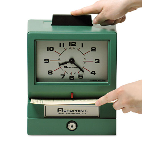
By the mid-century, time clocks had become somewhat simpler. No longer did the machine do the plotting for you. Now you put them in sideways, in the front, and use the indicator to get the punch in the right spot. It’s not hard to imagine why these gave way to more modern methods like fingerprint readers, or in my case, mag-stripe cards.
This is the type of time clock I intend to buy for myself, though I’m having trouble deciding between the manual model where you get to push a large button like this one, and the automatic version. I’d still like to build a time clock, too, for all the finesse and detail it could have by comparison. So honestly, I’ll probably end up doing both. Perhaps you’ll read about it on these pages one day.
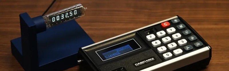
Have you heard the saying “the problem is the solution”? It seems to originate in the permaculture movement, but it can apply equally well to electronics. Take the problem [shiura] had: a Casio Mini CM-602 that had let out the magic smoke. The solution was a twofer: rebuild the Casio into a modern number cruncher with Reverse Polish Notation (RPN), and save the Vacuum Fluorescent Display (VFD) for a gorgeous WiFi clock.
[shiura]’s write-up includes a helpful guide for reverse engineering the pins on this sort of VFD, if you don’t happen to have the same model calculator (or VFD tube) they’re working with. If you’ve done this sort of thing, you know what to expect: power it up and kill power to the pins, one by one, to map out which segments or characters go out, thereby identifying the anodes and grid electrodes. The cathodes had already been ID’d from looking at the PCB. After that it’s just a matter of wiring the VFD to an ESP32 via a transistor array to get the voltages right, and voila! Clock. The code and case design files for this clock — including an editable .blend — are available via GitHub.
The calculator half of the project is an incredibly elegant hack that relies on the fact that the Casio’s CPU has the same pin pitch as modern micros: 2.54 mm, or 0.1″, so an RP2040 zero can sit in the footprint of the original CPU, scanning the keypads with its GPIO. Then an I2C display is separately wired up to replace the clockified VFD. Perhaps some driver circuitry for the VFD died, or [shiura] salvaged the display before deciding to save the calculator, because otherwise we see no reason why this brain transplant couldn’t be done while keeping the original display. Admittedly having two lines on the display instead of one make the “new” calculator a tad more usable. The code for that is also available on GitHub, and while the readme is in Japanese, machine translations have gotten pretty good and the code is quite readable on its own.
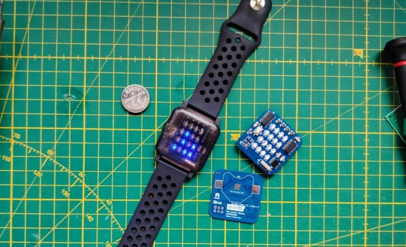
Over the decades we have seen many DIY clocks and wrist watches presented, but few are as likely to get you either drawing in the crowds, or quietly snickered at behind your back, as a binary watch of some description does. A wrist watch like [qewer]’s qron0b project which also uses BCD encoding to display the current time is among our more rare project types here, with us having to go all the way back to 2018 for a similar project as well as a BCD desk clock.
As is typical, a single CR2032 coin cell powers the entire PCB, with an ATtiny24A or compatible as the MCU, a DS1302 RTC and the requisite 4×4 LED matrix to display the hours and minutes. Technically three LEDs are unneeded here, but it looks nicely symmetrical this way, and the extra LEDs can be used for other tasks as the firmware is expanded from the current setting and reading of the time.
The AVR C firmware can be found in the above linked GitHub repository, along with the KiCad PCB project and FreeCAD design files for the watch body. The body accepts a 22 mm GT2/GT3-style watch strap to complete the assembly. With a single CR2032 you’re assured of at least a few months of runtime.