Reading view

There are new articles available, click to refresh the page.

SSH over USB on a Raspberry Pi

The edge of a laptop is shown with a USB cable plugged into it. the other end of the cable is plugged into a Raspberry Pi Zero.

Setting up access to a headless Raspberry Pi is one of those tasks that should take a few minutes, but for some reason always seems to take much longer. The most common method is to configure Wi-Fi access and an SSH service on the Pi before starting it, which can go wrong in many different ways. This author, for example, recently spent a few hours failing to set up a headless Pi on a network secured with Protected EAP, and was eventually driven to using SSH over Bluetooth. This could thankfully soon be a thing of the past, as [Paul Oberosler] developed a package for SSH over USB, which is included in the latest versions of Raspberry Pi OS.

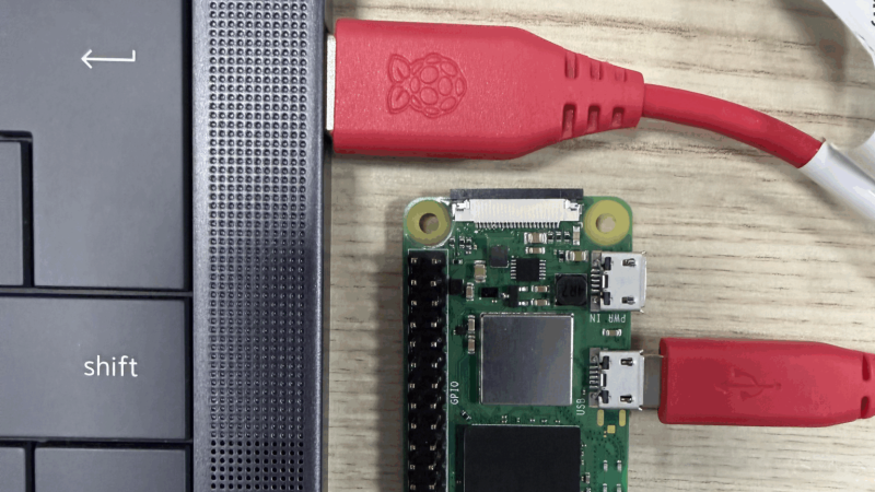
The idea behind rpi-usb-gadget is that a Raspberry Pi in gadget mode can be plugged into a host machine, which recognizes it as a network adapter. The Pi itself is presented as a host on that network, and the host machine can then SSH into it. Additionally, using Internet Connection Sharing (ICS), the Pi can use the host machine’s internet access. Gadget mode can be enabled and configured from the Raspberry Pi Imager. Setting up ICS is less plug-and-play, since an extra driver needs to be installed on Windows machines. Enabling gadget mode only lets the selected USB port work as a power input and USB network port, not as a host port for other peripherals.

An older way to get USB terminal access is using OTG mode, which we’ve seen used to simplify the configuration of a Pi as a simultaneous AP and client. If you want to set up headless access to Raspberry Pi desktop, we have a guide for that.

Thanks to [Gregg Levine] for the tip!

Tamper Detection with Time-Domain Reflectometry

A pair of printed circuit boards are shown against a pink background. The right circuit board is plugged into a USB cable, and has several LED indicators on. The left board is plugged into the other at 45-degree angle, and has no visible components.

For certain high-security devices, such as card readers, ATMs, and hardware security modules, normal physical security isn’t enough – they need to wipe out their sensitive data if someone starts drilling through the case. Such devices, therefore, often integrate circuit meshes into their cases and regularly monitor them for changes that could indicate damage. To improve the sensitivity and accuracy of such countermeasures, [Jan Sebastian Götte] and [Björn Scheuermann] recently designed a time-domain reflectometer to monitor meshes (pre-print paper).

Many meshes are made from flexible circuit boards with winding traces built into the case, so cutting or drilling into the case breaks a trace. The problem is that most common ways to detect broken traces, such as by resistance or capacitance measurements, aren’t easy to implement with both high sensitivity and low error rates. Instead, this system uses time-domain reflectometry: it sends a sharp pulse into the mesh, then times the returning echoes to create a mesh fingerprint. When the circuit is damaged, it creates an additional echo, which is detected by classifier software. If enough subsequent measurements find a significant fingerprint change, it triggers a data wipe.

The most novel aspect of this design is its affordability. An STM32G4-series microcontroller manages the timing, pulse generation, and measurement, thanks to its two fast ADCs and a high-resolution timer with sub-200 picosecond resolution. For a pulse-shaping amplifier, [Jan] and [Björn] used the high-speed amplifiers in an HDMI redriver chip, which would normally compensate for cable and connector losses. Despite its inexpensive design, the circuit was sensitive enough to detect when oscilloscope probes contacted the trace, pick up temperature changes, and even discern the tiny variations between different copies of the same mesh.

It’s not absolutely impossible for an attacker to bypass this system, nor was it intended to be, but overcoming it would take a great deal of skill and some custom equipment, such as a non-conductive drill bit. If you’re interested in seeing such a system in the real world, check out this teardown of a payment terminal. One of the same authors also previously wrote a KiCad plugin to generate anti-tamper meshes.

Thanks to [mark999] for the tip!

Self-Powered Top Spins for Hours

An aluminium top is shown spinning on a plastic disk in front of a tablet showing the text "2:07:49.5"

The meaning of Inception’s ending famously revolves around a top which spins forever in dreams, but in real life comes to a stop like any other top. Any other top, that is, except for [Aaed Musa]’s self-spinning top, which can continuously spin for about two hours before coming to a stop.

The one constraint was that every functional component had to be contained within the top’s shell, and [Aaed]’s first approach was to build a reaction wheel into the top. When a motor accelerates a weighted wheel, conservation of angular momentum applies an equal and opposite torque to the motor. The problem is that motors eventually reach a top speed and stop accelerating, which puts an end to the torque. This is known as saturation, and the only way to desaturate a reaction wheel is to slow it down, which counteracts the originally generated torque. [Aaed] originally planned to mount the motor in a one-way bearing, which would let it bleed off speed without producing torque against the rest of the top, but it was rather choppy in practice.

The solution occurred to [Aaed] while watching the aforementioned final scene, when it occurred to him that the wobbling of a top could actually generate rotation. A prototype proved that an off-center weight rotating at a constant speed did successfully spin the top by rotating the center of mass, and after that, it was a matter of incremental testing and improvement. A higher moment of inertia worked better, as did a lower center of gravity and a tip made from a hard, low-friction silicon nitride ball bearing. He made housings out of both 3D-printed plastic and CNC-milled aluminium, which each contained a tiny brushless motor, an electric speed controller, a microcontroller, and a small rechargeable lithium battery.

If you allow for external power, you can make the top itself the rotor of a motor, and drive it from a base. Alternatively, if you levitate your top in a vacuum, it could spin for longer than recorded history.

Accurately Aiming Audio with an Ultrasonic Array

A device rather resembling a megaphone is lying on a table. The handle is made of black plastic. The horn is made of grey plastic, is hexagonal, and is not tapered. At the back of the horn is an array of silver ultrasonic transducers.

When [Electron Impressions] used a powerful ultrasonic array to project a narrow beam of sound toward a target, he described it as potentially useful in getting someone’s attention from across a crowded room without disturbing other people. This is quite a courteous use compared to some of the ideas that occur to us, and particularly compared to the crowd-control applications that various militaries and police departments put directional speakers to.

Regardless of how one uses it, however, the physics behind such directional speakers is interesting. Normal speakers tend to disperse their sound widely because the size of the diaphragm is small compared to the wavelength of the sound they produce; just like light waves passing through a pinhole or thin slit, the sound waves diffract outwards in all directions from their source. Audible frequencies have wavelengths too long to make a handheld directional speaker, but ultrasonic waves are short enough to work well; [Electron Impressions] used 40 kHz, which has a wavelength of just eight millimeters. To make the output even more directional, he used an array of evenly-spaced parallel emitters, which interfere constructively to the front and destructively to the sides.

Ultrasound shouldn’t be audible, but sound waves travel slightly faster in high-pressure air than in low-pressure air. Since sound waves are just variations in pressure, this means that at high enough amplitudes, they change their own shape as they travel through air, tending to merge together somewhat into lower-frequency waves. When amplitude modulation is applied to the ultrasonic signal, the air itself demodulates it into audible sound (the audio quality isn’t wonderful, but still recognizable). [Electron Impressions] demonstrated the completed device, and it’s possible to hear a clear difference in intensity when it’s pointed at the microphone. It’s also possible to reflect the sound beam off hard surfaces, though multiple reflections tend to decrease the directivity when used indoors.

The circuit itself is very similar to another which we’ve covered before, down to the 555 timer used in the ultrasonic driver, and the overall approach is very reminiscent of this directional ultrasonic array.

Is the Theory of Special Relativity Wrong?

A red-and-blue image of a nebula is shown, shaped somewhat like an eye, with a plume of gas emitting from the center.

There’s an adage coined by [Ian Betteridge] that any headline ending in a question mark can be answered by the word “No”. However, Lorentz invariance – the theory that the same rules of physics apply in the same way in all frames of reference, and an essential component of special relativity – has been questioned for some time by researchers trying to unify general relativity and quantum field theory into a theory of quantum gravity. Many theories of quantum gravity break Lorentz invariance by giving photons with different energy levels very slightly different speeds of light – a prediction which now looks less likely since researchers recently analyzed gamma ray data from pulsed astronomical sources, and found no evidence of speed variation (open-access paper).

The researchers specifically looked for the invariance violations predicted by the Standard-Model Extension (SME), an effective field theory that unifies special relativity with the Standard Model. The variations in light speed which it predicts are too small to measure directly, so instead, the researchers analyzed gamma ray flare data collected from pulsars, active galactic nuclei, and gamma-ray bursts (only sources that emitted gamma rays in simultaneous pulses could be used). Over such great distances as these photons had traveled, even slight differences in speed between photons with different energy levels should have added up to a detectable delay between photons, but none was found.

This work doesn’t disprove the SME, but it does place stricter bounds on the Lorentz invariance violations it allows, about one and a half orders of magnitude stricter than those previously found. This study also provides a method for new experimental data to be more easily integrated into the SME. Fair warning to anyone reading the paper: the authors call their work “straightforward,” from which we can only conclude that the word takes on a new meaning after a few years studying mathematics.

If you want to catch up on relativity and Lorentz invariance, check out this quick refresher, or this somewhat mind-bending explanation. For an amateur, it’s easier to prove general relativity than special relativity.


Top image: Crab Pulsar, one of the gamma ray sources analysed. (Credit: J. Hester et al., NASA/HST/ASU/J)

Taking a Look at Variable Vacuum Capacitors

A pair of glass vacuum tubes can be seen on a workbench, each with complex copper structures inside. One is mounted on top of a metal chassis with a motor and some other circuitry visible.

Variable capacitors may be useful, but the air gap that provides their capacitance is their greatest weakness. Rather than deal with the poor dielectric properties of air, some high-end variable capacitors replace it with a vacuum, which presents some obvious mechanical difficulties, but does give the resulting capacitor a remarkable quality factor, high-voltage performance, and higher capacitance for plate area than their air-gapped brethren. [Shahriar] of [The Signal Path] managed to acquire a pair of these and took a detailed look at their construction and performance in a recent video.

The vacuum capacitors don’t use quite the same parallel plate design as other variable capacitors. They instead make the plates out of interlaced concentric metal rings mounted in a vacuum tube. Both sets of rings are connected to terminals, one fixed and one capable of being pulled in or out on a threaded rod surrounded by an accordion-pleated copper seal. A nut on the outside pulls the rod out, and the interior vacuum pulls it in toward the other set of plates. Unfortunately, since the mobile terminal needs to be mechanically connected to some adjustment mechanism (such as someone’s hand), it can’t really be at a floating voltage. The mobile terminal needs to be grounded for safety. Alternatively, for automatic control, one of the capacitors had a chassis with a motor, gearing, and a positional encoder.

[Shahriar] also tested the capacitors with an impedance analyzer and lock-in amplifier. They had fairly low capacitance (for the one he tested, 36 pF at maximum and 16 pF at minimum), but the dissipation factor was so low and the DC impedance so high that they couldn’t be meaningfully measured. He also tested one at 5000 volts and found almost no dissipation.

We recently saw another video going over a lesser-known feature of normal air-gap variable capacitors and another new non-standard variable capacitor design. On the opposite end of the fanciness spectrum might be this variable capacitor built out of aluminium cans.

A New Kind of Inductively-damped Compass

A man is shown standing in a wooded area, in front of a stone wall, facing toward the camera. To the left of him, on a rock, are a selection of compasses. Further to the left, another scene is shown, of two compasses. One has a brass-colored metal ring around it, and a timer above it reads 00:04:19. A timer above the other reads 01:47:02.

At some point during our primary school careers, most of us probably constructed a simple compass, often by floating a magnetized needle on a cork in a cup of water. The water in such a configuration not only lets the needle spin without friction, but also dampens out (so to speak) the needle’s tendency to swing back and forth across the north-south line. Liquid-filled compasses use the same principle, but even well-made compasses can develop bubbles when exposed to temperature or pressure variations. Rather than accept this unsightly state of affairs, [The Map Reading Company] designed a new kind of liquid-free, inductively-damped compass.

It’s hard to design a compass that settles quickly, even if it uses a strong magnet, because the Earth’s own magnetic field is just so weak, and the stronger the internal magnet is, the more likely it is to be thrown off by nearby magnetic objects. As a result, they tend to swing, overshoot, and oscillate around their final orientation for some time. Most compasses use liquid to damp this, but a few, mostly military compasses, use a conductive baseplate instead: as the magnet moves, it induces eddy currents in the baseplate, which create a weak magnetic field opposing its motion, slowing the magnet down. Inductively-damped compasses don’t get bubbles, but they don’t let you see a map through the baseplate. [The Map Reading Company] dealt with this by making the baseplate transparent and surrounding the compass needle with a ring of high-conductivity copper alloy. This gave him a clear baseplate compass for easy map reading which would never develop bubbles. It’s a simple hack, and should be easy to replicate, but it still seems to be a new design. In fact, [The Map Reading Company] is releasing most of the design to the public domain. Anyone can build this design.

If this prompts your interest in compasses, check out the Earth inductor compass. We’ve also seen a visualization of the eddy currents that damp these oscillations, and even seen them used to drive a bike.

Thanks to [Mel] for the tip!

Simplifying the SmartKnob

A man's hands are shown holding a black device. A white knob is in the center of the device, and above the knob in a central protrusion from the rest of the device is a small, circular LCD device.

A knob can make a surprisingly versatile interface, particularly if it’s the SmartKnob, which builds a knob around a BLDC motor for programmable haptic response. It can rotate freely or with a set resistance, spring back to a fixed point when released, stick at detent points, and completely change its behavior as the interface demands. For people inexperienced in electronic assembly, though, smartknobs can be difficult to assemble. That’s why [Kokensha Tech] designed a simpler version, while at the same time letting it use a wider range of BLDC motors.

In addition to a motor, the original design used a magnetic encoder to detect position and a strain gauge to detect pressure on the knob. A circular LCD on the knob itself provided visual feedback, but it also required the motor to have a hollow center shaft. The LCD control wires running through the shaft proved tricky to assemble.  [Kokensha Tech] moved the display out of the knob and onto a separate breakout board, which plugs into the controller board. This greatly broadens the range of compatible motors, since they no longer need a hollow shaft.

The motor now fits on a separate carrier board, which makes it easier to swap out different motors. The carrier board has mounting holes sized for a wide variety of motors, and four different types of motor connectors. [Kokensha Tech] also redesigned the rest of the PCB for easier soldering, while avoiding components with narrow pin spacing whenever possible. The original design used a LILYGO T-micro32 Plus MCU. The ESP32 is both cheaper and easier to solder, so it was a no-brainer to swap it in. 

We’ve covered the original SmartKnob before, including a more in-depth look at its design. We’ve also seen another project use BLDCs and field-oriented control to make haptic knobs.

Testing Laughing Gas for Rocket Propellant

A man's gloved hand is need adjusting the valve on a cylinder, from which a clear plastic tube extends. The man's other hand is seen holding the the other end of the tube in front of a dish of burning wax, which is flaring brightly.

Nitrous oxide’s high-speed abilities don’t end with racing cars, as it’s a powerful enough oxidizer to be a practical component of rocket propellant. Since [Markus Bindhammer] is building a hybrid rocket engine, in his most recent video he built and tested a convenient nitrous oxide dispenser.

The most commercially available form of nitrous oxide is as a propellant for whipped cream, for which it is sold as “cream chargers,” basically small cartridges of nitrous oxide which fit into cream dispensers. Each cartridge holds about eight grams of gas, or four liters at standard temperature and pressure. To use these, [Markus] bought a cream dispenser and disassembled it for the cartridge fittings, made an aluminium adapter from those fittings to a quarter-inch pipe, and installed a valve. As a quick test, he fitted a canister in, attached it to a hose, lit some paraffin firelighter, and directed a stream of nitrous oxide at it, upon which it burned much more brightly and aggressively.

It’s not its most well-known attribute in popular culture, but nitrous oxide’s oxidizing potential is behind most of its use by hackers, whether in racing or in rocketry. [Markus] is no stranger to working with nitrogen oxides, including the much more aggressively oxidizing nitrogen dioxide.

Tying up Loose Ends on a Rope-based Robot Actuator

A round, 3D-printed motor housing is shown, with one flattened side holding a fan mount. A circular plate is mounted above the face of the housing, and a cord runs around it and pulleys on the side of the housing.

One of the perennial challenges of building robots is minimizing the size and weight of drive systems while preserving power. One established way to do this, at least on robots with joints, is to fit each joint with a quasi-direct-drive motor integrating a brushless motor and gearbox in one device. [The 5439 Workshop] wanted to take this approach with his own robot project, but since commercial drives were beyond his budget, he designed his own powerful, printable actuator.

The motor reducing mechanism was the biggest challenge: most quasi-direct drives use a planetary gearbox, but this would have been difficult to 3D-print without either serious backlash or limited torque. A cycloidal drive was an option, but previous printable cycloidal drives seemed to have low efficiency, and they didn’t want to work with a strain-wave gearing. Instead, he decided to use a rope drive (this seems to be another name for a kind of Capstan drive), which doesn’t require particularly strong materials or high precision. These normally use a rope wound around two side-by-side drums, which are difficult to integrate into a compact actuator, but he solved the issue by putting the drums in-line with the motor, with two pairs of pulleys guiding the rope between them in a “C” shaped path.

The actual motor is a hand-wound stator inside a 3D-printed rotor with magnets epoxied into it. The printed rotor proved problematic when the attraction between the rotor and magnets caused it to flex and scrape against the housing, and it eventually had to be reinforced with some thin metal sheets. After fixing this, it reached five Newton-meters of torque at one amp and nine Newton-meters at five amps. The diminishing returns seem to be because the 3D-printed pulley wheels broke under higher torque, which should be easy to fix in the future.

This looks like a promising design, but if you don’t need the output shaft inline with the motors, it’s probably easier to build a simple Capstan drive, the mathematics of which we’ve covered before. Both makers we’ve previously seen build Capstan drives used them to make robot dogs, which says something for their speed and responsiveness.

❌