❌

Reading view

There are new articles available, click to refresh the page.

Vacuum Fluorescent Displays Explained

After having been sent a vacuum fluorescent display (VFD) based clock for a review, [Anthony Francis-Jones] took the opportunity to explain how these types of displays work.

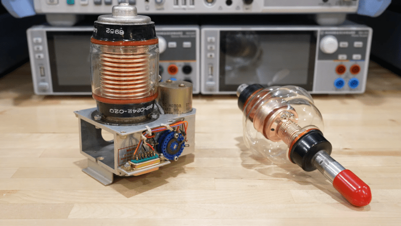
Although VFDs are generally praised for their very pleasant appearance, they’re also relatively low-power compared to the similar cathode ray tubes. The tungsten wire cathode with its oxide coating produces the electrons whenever the relatively low supply voltage is applied, with a positively charged grid between it and the phosphors on the anode side inducing the accelerating force.

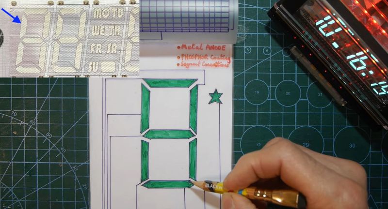
Although a few different digit control configurations exist, all VFDs follow this basic layout. The reason why they’re also called β€˜cold cathode’ displays is because the cathode doesn’t heat up nearly as hot as those of a typical vacuum tube, at a mere 650 Β°C. Since this temperature is confined to the very fine cathode mesh, this is not noticeable outside of the glass envelope.

While LCDs and OLED displays have basically eradicated the VFD market, these phosphor-based displays still readily beat out LCDs when it comes to viewing angles, lack of polarization filter, brightness and low temperature performance, as LC displays become extremely sluggish in cold weather. Perhaps their biggest flaw is the need for a vacuum to work, inside very much breakable glass, as this is usually how VFDs die.

Driving A DAC Real Fast With A Microcontroller

By: Lewin Day

Normally, if you want to blast out samples to a DAC in a hurry, you’d rely on an FPGA, what with their penchant for doing things very quicky and in parallel. However, [Anabit] figured out a way to do the same thing with a microcontroller, thanks to the magic of the Raspberry Pi Pico 2.

The design in question is referred to as the PiWave 150 MS/s Bipolar DAC, and as the name suggests, it’s capable of delivering a full 150 million samples per second with 10, 12, or 14 bits of resolution. Achieving that with a microcontroller would normally be pretty difficult. In regular linear operation, it’s hard to clock bits out to GPIO pins at that sort of speed. However, the Raspberry Pi Pico 2 serves as a special case in this regard, thanks to its Programmable I/O (PIO) subsystem. It’s a state machine, able to be programmed to handle certain tasks entirely independently from the microcontroller’s main core itself, and can do simple parallel tasks very quickly. Since it can grab data from RAM and truck it out to a bank of GPIO pins in a single clock cycle, it’s perfect for trucking out data to a DAC in parallel at great speed. The Pi Pico 2’s clock rate tops out at 150 MHz, which delivers the impressive 150 MS/s sample rate.

The explainer video is a great primer on how this commodity microcontroller is set up to perform this feat in detail. If you’re trying for accuracy over speed, we’ve explored solutions for that as well. Video after the break.

Espressif Introduces the ESP32-E22 Wi-Fi 6E and Bluetooth Co-Processor

Espressif has unveiled its latest major chip in the form of the ESP32-E22. Officially referred to as a Radio Co-Processor (RCP), it’s intended to be used via its PCIe 2.1 or SDIO 3.0 host interface to provide wireless communications to an SoC or similar.

This wireless functionality includes full WiFi 6E functionality across all three bands, 160 MHz channel bandwidth and 2Γ—2 MU-MIMO, making it quite a leap from the basic WiFi provided by e.g. the ESP32-S* and -C* series. There is also Bluetooth Classic and BLE 5.4 support, which is a relief for those who were missing Bluetooth Classic in all but the original ESP32 for e.g. A2DP sinks and sources.

The ESP32-E22 processing grunt is provided by two proprietary Espressif RISC-V CPU cores that can run at 500 MHz. At this point no details appear to be available about whether a low-power core is also present, nor any additional peripherals. Since the graphics on the Espressif PR article appear to be generic, machine-generated images – that switch the chip’s appearance from a BGA to an LQFP package at random – there’s little more that we can gather from there either.

Currently Espressif is making engineering samples available to interested parties after presumed vetting, which would indicate that any kind of public release will still be a while off. Whether this chip would make for an interesting stand-alone MCU or SoC along the lines of the -S3 or -P4 will remain a bit of a mystery for a bit longer.

Thanks to [Rogan] for the tip.

What to do With a Flash-less ESP32-C3 Super Mini Board?

In an update video by [Hacker University] to an earlier video on ESP32-C3 Super Mini development boards that feature a Flash-less version of this MCU, the question of adding your own Flash IC to these boards is addressed. The short version is that while it is possible, it’s definitely not going to be easy, as pins including SPIHD (19) and SPICLK (22) and SPIQ (24) are not broken out on the board and thus require one to directly solder wires to the QFN pads.

Considering how sketchy it would be to have multiple wires running off to an external Flash IC, this raises many questions about the feasibility, as well as cost-effectiveness. Some in the comments to the video remark that instead you may as well swap the MCU with a version that does contain built-in Flash, but this is countered with the argument that a new ESP32-C3 Super Mini board with the right MCU costs as much as a loose MCU from your favorite purveyor of ICs.

Ultimately this lends some credence to calling these zero Flash Super Mini boards a β€˜scam’, as their use cases would seem to be extremely limited and their Flash-less nature very poorly advertised.

ESP32-c3 reference implementation with external flash. (Credit: Espressif)
ESP32-C3 reference implementation with external flash. (Credit: Espressif)

WCH CH32M030: Another Microcontroller To Watch Out For

One of the joys of writing for Hackaday comes in following the world of new semiconductor devices, spotting interesting ones while they are still just entries on manufacturer websites, and then waiting for commonly-available dev boards. With Chinese parts there’s always a period in which Chinese manufacturers and nobody else has them, and then they quietly appear on AliExpress.

All of which brings us to the WCH CH32M030, a chip that’s been on the radar for a while and has finally broken cover. It’s the CH32 RISC-V microcontroller you may be familiar with, but with a set of four half-bridge drivers on board for running motors. A handy, cheap, and very smart motor controller, if you will.

There’s been atΒ  least one Chinese CH32M030 dev board (Chinese language) online for a while now, but the one listed on AliExpress appears to be a different design. At the time of writing the most popular one is still showing fewer than 20 sales, so we’re getting in at the ground floor here.

We think this chip is of interest because it has the potential to be used in low price robotic projects, replacing as it does a couple of parts or modules in one go. If you use it, we’d like to hear from you!

Looking at a Real Fake Raspberry Pi RP2040 Board

Since the RP2040 microcontroller is available as a stand-alone component, it’s easy enough for third parties to churn out their own variations β€” or outright clones of β€” the Raspberry Pi Pico. Thus we end up with for example AliExpress sellers offering their own versions that can be significantly cheaper than the genuine article. The ones that [electronupdate] obtained for a test and decapping session cost just $2.25 a pop.

RP2 B0 stepping imprinted on the die shot.

As can be seen in the top image, the board from AliExpress misses the Raspberry Pi logo on the silkscreen for obvious reasons, but otherwise appears to feature an identical component layout. The QSPI Flash IC is marked on the die as BY250156FS, identifying it as a Boya part.

Niggles about flash ROM quality aside, what’s perhaps most interesting about this teardown is what eagle-eyed commentators spotted on the die shot of the RP2040. Although on the MCU the laser markings identify the RP2040 as a B2 stepping, the die clearly identifies it as an β€˜RP2 B0’ part, meaning B0 stepping. This can be problematic when you try to use the USB functionality due to hardware USB bugs in the B0 and B1 steppings.

As they say, caveat emptor.

Fixing a KS Jive DAB Radio with a Dash of Fake ICs

The radio unit after a successful repair. (Credit: Buy it Fix it, YouTube)

The exciting part about repairing consumer electronics is that you are never quite sure what you are going to find. In a recent video by [Mick] of Buy it Fix it on YouTube the subject is a KS Jive radio that throws a few curve balls along the way. After initially seeing the unit not power on with either batteries or external power, opening it up revealed a few loose wires that gave the false hope that it would be an easy fix.

As is typical, the cause of the unit failing appears to have been a power surge that burned out a trace and obliterated the 3.3V LDO and ST TDA7266P amplifier. While the trace was easily fixed, and AMS1117 LDOs are cheap and plentiful, the amplifier chip turned out to be the real challenge on account of being an EOL chip.

The typical response here is to waddle over to purveyors of scrap hardware, like AliExpress sellers. Here [Mick] bought a β€˜new’ TDA7266P, but upon receiving his order, he got suspicious after comparing it with the busted original. As can be seen in the top image, the markings, logo and even typeface are wildly different. Thus [Mick] did what any reasonable person does and x-rayed both chips to compare their internals.

X-ray of the real vs fake ST TDA7266P ICs. (Credit: Buy it Fix it, YouTube)

On the left you can see the dead original amplifier, with what looks like a big mark on the die where the power event destroyed part of it. What’s also apparent from this and the other x-ray shots is that neither the die size, bond wires, nor the physical package’s pins match up. The unusual connections of the fake IC led [Mick] to conclude that it was likely an ST VNQ5E050AK-E quad-channel high-side driver, or at least something very similar to it.

After taking a CNC milling machine to the real and fake chips for additional comparison and a crude decapping, he was still left in a bind, as finding a replacement IC turned out to be basically impossible. Almost, that is, as Mouser turned out to still have the TDA7266P13TR, tape-reel version in stock, with a few left.

This is apparently the same IC, but the cut-reel variety. Interestingly, when tossing this replacement in the x-ray machine, it showed to have a bigger die than the dead ST amplifier IC, which could be due to having been produced with a different process node or so. Regardless, with the original part the radio sprung right back to life, but it shows once again how many chips are being remarked by AliExpress sellers to be something that they are definitely not. Caveat emptor, once more.

Taking a Look at Variable Vacuum Capacitors

A pair of glass vacuum tubes can be seen on a workbench, each with complex copper structures inside. One is mounted on top of a metal chassis with a motor and some other circuitry visible.

Variable capacitors may be useful, but the air gap that provides their capacitance is their greatest weakness. Rather than deal with the poor dielectric properties of air, some high-end variable capacitors replace it with a vacuum, which presents some obvious mechanical difficulties, but does give the resulting capacitor a remarkable quality factor, high-voltage performance, and higher capacitance for plate area than their air-gapped brethren. [Shahriar] of [The Signal Path] managed to acquire a pair of these and took a detailed look at their construction and performance in a recent video.

The vacuum capacitors don’t use quite the same parallel plate design as other variable capacitors. They instead make the plates out of interlaced concentric metal rings mounted in a vacuum tube. Both sets of rings are connected to terminals, one fixed and one capable of being pulled in or out on a threaded rod surrounded by an accordion-pleated copper seal. A nut on the outside pulls the rod out, and the interior vacuum pulls it in toward the other set of plates. Unfortunately, since the mobile terminal needs to be mechanically connected to some adjustment mechanism (such as someone’s hand), it can’t really be at a floating voltage. The mobile terminal needs to be grounded for safety. Alternatively, for automatic control, one of the capacitors had a chassis with a motor, gearing, and a positional encoder.

[Shahriar] also tested the capacitors with an impedance analyzer and lock-in amplifier. They had fairly low capacitance (for the one he tested, 36 pF at maximum and 16 pF at minimum), but the dissipation factor was so low and the DC impedance so high that they couldn’t be meaningfully measured. He also tested one at 5000 volts and found almost no dissipation.

We recently saw another video going over a lesser-known feature of normal air-gap variable capacitors and another new non-standard variable capacitor design. On the opposite end of the fanciness spectrum might be this variable capacitor built out of aluminium cans.

Texas Instruments Explain Low-Dropout Linear Voltage Regulators

An LDO schematic and some notes about their features

Today in power electronics, the folks over at Texas Instruments have put together a video covering low-dropout (LDO) linear regulators.

For a hacker, power is pretty fundamental, so it behooves us to know a little bit about what our options are when it comes time to regulate power to our projects. In this video [Alex Hanson] from Texas Instruments runs us through the linear voltage regulators known as low-dropout regulators (LDOs). It turns out that LDOs are often a poor choice for voltage regulation because they are inefficient when compared to switching regulator alternatives and can be more expensive too.

So when might you use an LDO? In very low power situations where heat and efficiency doesn’t matter very much. LDOs operate best when the input voltage is very near the output voltage and when current demands are low (roughly speaking less than ~50 mA is okay, ~500 mA is maximum, and some applications will support 1 to 3 A, although not with great efficiency and in this case thermal emissions β€” or magic smoke! β€” will become an issue).

What LDOs bring to the table is relatively clean and low-noise voltage as well as low dropout voltage (the minimum difference between the input and output voltage needed for regulation), which is their defining feature. What’s more with an appropriate output capacitor they can react quickly to load changes and they usually emit minimal EMI. LDOs are not about efficiency, they are about quality, simplicity, and control.

You might like to read more about when linear regulators might be the right choice or what your other options are.

❌