Reading view

There are new articles available, click to refresh the page.

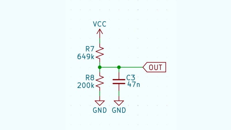
An Online Repository for KiCad Schematics

By: Ian Bos

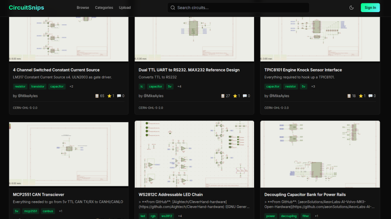
In the desktop 3D printing world, we’re fortunate to have multiple online repositories of models that anyone can load up on their machine. Looking to create a similar experience but for electronic projects, [Mike Ayles] created CircuitSnips — a searchable database of ready-to-use KiCad schematics available under open source licenses.

Looking for reference designs for LiPo chargers? CircuitSnips has you covered. Want to upload your own design so others can utilize it? Even better. Currently, there are over four thousand circuits on CircuitSnips, although not all have been put there purposely. To get the project off the ground, [Mike] scrapped GitHub for open source KiCad projects. While this doesn’t run afoul of the licensing, there’s a mechanism in place for anyone who wants to have their project removed from  the repository.

To scrape the depths of GitHub, [Mike] had to simplify the text expression for the KiCad projects using a tool he’s since released. For anyone so inclined, he’s even put the entire site on GitHub for anyone who wants to try their hand at running it locally.

CircuitSnaps fills a very specific space to post your circuit diagrams, but if you’re looking for somewhere to host your complete designs, we can’t fail to mention Hackaday’s own repository for hardware projects and hacks!

KiDoom Brings Classic Shooter to KiCad

As the saying goes: if it has a processor and a display, it can run DOOM. The corollary here is that if some software displays things, someone will figure out a way to make it render the iconic shooter. Case in point KiDoom by [Mike Ayles], which happily renders DOOM in KiCad at a sedate 10 to 25 frames per second as you blast away at your PCB routing demons.

Obviously, the game isn’t running directly in KiCad, but it does use the doomgeneric DOOM engine in a separate process, with KiCad’s PCB editor handling the rendering. As noted by [Mike], he could have used a Python version of DOOM to target KiCad’s Python API, but that’s left as an exercise for the reader.

Rather than having the engine render directly to a display, [Mike] wrote code to extract the position of sprites and wall segments, which is then sent to KiCad via its Python interface, updating the view and refreshing the ‘PCB’. Controls are as usual, though you’ll be looking at QFP-64 package footprints for enemies, SOIC-8 for decorations and SOT-23-3 packages for health, ammo and keys.

If you’re itching to give it a try, the GitHub project can be found right here. Maybe it’ll bring some relief after a particularly frustrating PCB routing session.

A PCB Can Be A Hydrofoil, If it Really Wants To

Styrofoam watercraft, PCB hydrofoil

You know those old cliche that the younger generations have begun to cynically despise: “follow your dreams!” “You can be anything you put your mind to!” — well, perhaps they are true on occasion. For instance when [rctestflight] had PCBs that dreamed of becoming a hydrofoil, he found a way to make that dream come true.

It’s kind of obvious in retrospect: printed circuit boards are made of FR4, which is a form of fiberglass, and you know what else is commonly made of fiberglass? Boats. So yes, the material is suited for this task. The fact that solder joints hold up to use in a little remote-control hydrofoil is less obvious, but good to know. It certainly makes for easier assembly for those of us who have developed an allergy to epoxy.

Ease of assembly wasn’t really the point here: the point was that by making the “mast” of the hydrofoil out of PCB– that’s the part that holds the underwater wing– [rctestflight] figured he could (shock!) print a circuit onto it. Specifically, a liquid-level sensor, and because microcontrollers are so cheap these days he went the “total overkill” route of embedding an ESP32 on each mast. He started with a resistive sensor, but since those self-corrode too quickly, the team switched to a capacitive sensor that doesn’t need to form a galvanic cell in salt water. Come to think of it, that might still be a problem with the solder joint between the PCBs. Good thing nobody will be riding this one.

Having such a sensor and brain close-coupled allows for a faster control loop than the sonar [rctestflight] had previously been using to control his hydrofoil’s altitude.. Pivoting each mast with its own servo made for a smooth flight over the water— well, once they got the PID tuning set, anyway. Check it out in the video embedded below.

We’ve seen PCB used for enclosures before, and even the chassis of a rover, but using it for a hydrofoil is a new hack.

Making Actually Useful Schematics in KiCad

Schematic of a voltage divider

[Andrew Greenberg] has some specific ideas for how open-source hardware hackers could do a better job with their KiCad schematics.

In his work with students at Portland State University, [Andrew] finds his students both reading and creating KiCad schematics, and often these schematics leave a little to be desired.

To help improve the situation he’s compiling a checklist of things to be cognisant of when developing schematics in KiCad, particularly if those schematics are going to be read by others, as is the hope with open-source hardware projects.

In the video and in his checklist he runs us through some of the considerations, covering: visual design best practices; using schematic symbols rather than packages; nominating part values; specific types of circuit gotchas; Design for Test; Design for Fail; electric rule checks (ERC); manufacturer (MFR), part number (MPN), and datasheet annotations for Bill of Materials (BOM); and things to check at the end of a design iteration, including updating the date and version number.

(Side note: in the video he refers to the book The Visual Display of Quantitative Information which we have definitely added to our reading list.)

Have some best practices of your own you would like to see on the checklist? Feel free to add your suggestions!

If you’re interested in KiCad you might like to read about what’s new in version 9 and how to customize your KiCad shortcut keys for productivity.

(Neural) Networking with a Business Card

A circuit board in the shape of a business card is shown. The circuitry is confined to the left side of the board, and the rest is used for text.

A PCB business card is a great way for electrical engineers to impress employers with their design skills, but the software they run can be just as impressive as the card itself. As a programmer with an interest in embedded machine learning, [Dave McKinnon] wanted a card that showcased his skills, so he designed one that runs voice recognition.

[Dave] specifically wanted to run a neural network on his card, but needed to make it small enough to run on a microcontroller. Voice recognition looked like a good fit for this, since audio can be represented with relatively little data, a microphone is cheap and easy to add to a circuit board, and there was already an example of someone running such a voice recognition network on an Arduino. To fit the neural network into 46 kB, it only distinguishes the words “one” through “nine,” and displays its guess on an LED seven-segment display. [Dave] first prototyped the system with an Arduino, then designed the circuit board around an RP2040.

The switch from Arduino to the RP2040 brought with it a mysterious change: it would usually recognize the word “eight,” but none of the other numbers. After much investigation, it turned out that the new circuit was presenting samples at a much higher rate than the older one had, which was throwing the network off. [Dave] increased the sampling period and had the user speak the numbers slowly, which solved the issue.

The microcontroller was well chosen; the RP2040 is good enough for machine learning that there are dev boards explicitly designed for it, and even comparatively less powerful Arduino boards can do surprisingly good voice recognition. On the hardware side, [Dave] cited some of the Linux business cards we’ve seen as inspiration.

The Value of a Worked Example

I was looking over the week’s posts on Hackaday – it’s part of my job after all – and this gem caught my eye: a post about how to make your own RP2040 development board from scratch. And I’ll admit that my first thought was “why would you ever want to do that?” (Not a very Hackaday-appropriate question, honestly.) The end result will certainly cost more than just buying a Pi Pico off the shelf!

Then it hit me: this isn’t a project per se, but rather [Kai] was using it as an test run to learn the PCB-production toolchain. And for that, replicating a Pico board is perfect, because the schematics are easily available. While I definitely think that a project like this is a bit complicated for a first PCB project – I’d recommend making something fun like an SAO – the advantage of making something slightly more involved is that you run into all of the accompanying problems learning experiences. What a marvelous post-complete-beginner finger exercise!

And then it hit me again. [Kai]’s documentation of everything learned during the project was absolutely brilliant. It’s part KiCAD tutorial, part journal about all the hurdles of getting a PCB made, and just chock-full of helpful tips along the way. The quality of the write-up turns it from being just a personal project into something that can help other people who are in exactly the same boat, and I’m guessing that’s a number of you out there.

In the end, this was a perfect Hackaday project. Yes, it was “too simple” for those who have made their 30th PCB design. (Although I’d bet you could still pick up a KiCAD tip or two.) And yes, it doesn’t make economic sense to replicate mass-market devices in one-off. And of course, it doesn’t need that fun art on the board either. But wrap all these up together, and you get a superbly documented guide to a useful project that would walk you through 95% of what you’ll need to make more elaborate projects later on. Superb!

Surely you do “finger exercises” too. Why not write them up, and share the learning? And send them our way – we know just the audience who will want to read it.

This article is part of the Hackaday.com newsletter, delivered every seven days for each of the last 200+ weeks. It also includes our favorite articles from the last seven days that you can see on the web version of the newsletter. Want this type of article to hit your inbox every Friday morning? You should sign up!
❌