❌

Reading view

There are new articles available, click to refresh the page.

The Busch Electronic Digital-Technik 2075 Digital Lab from the 1970s

The box of the Busch Electronic Digital-Technik 2075

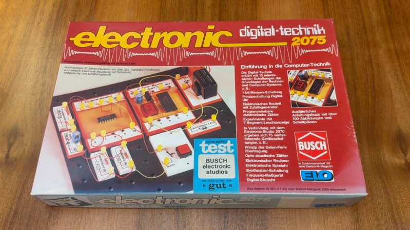
In a recent video, [Jason Jacques] demos the Busch Electronic Digital-Technik 2075 which was released in West Germany in the 1970s.

The Digital-Technik 2075 comes with a few components including a battery holder and 9 V battery, a push button, two 1 K resistors, a red LED, a 100 nF ceramic capacitor, a 100 Β΅F electrolytic capacitor, a quad NAND gate IC, and a counter module which includes an IC and a 7-segment display. The kit also comes with wires, plugs, a breadboard, and a tool for extracting modules.

The Digital-Technik 2075 doesn’t use the spring terminals we see in other project labs of the time, such as the Science Fair kits from Radio Shack, and it doesn’t use modular Denshi blocks, such as we saw from the Gakken EX-150, but rather uses wire in conjunction with yellow plastic plugs. This seems to work well enough.

In the video, after showing us how to do switch debouncing, [Jason] runs us through making a counter with the digital components and then getting the counter to reset after it counts to five. This is done using NAND gates. Before he gets stuck into doing a project he takes a close look at the manual (which is in German) including some of the advertisements for other project labs from Busch which were available at the time. As he doesn’t speak German [Jason] prints out an English translation of the manual before working through it.

We’ve heard from [Jason] at Hackaday in recent history when we saw his Microtronic Phoenix Computer System which referenced the 2090 Microtronic Computer System which was also made by Busch.

DIY Test Gear from 1981

We can’t get enough of [Bettina Neumryn’s] videos. If you haven’t seen her, she takes old electronics magazines, finds interesting projects, and builds them. If you remember these old projects, it is nostalgic, and if you don’t remember them, you can learn a lot about basic electronics and construction techniques. This installment (see below) is an Elektor digital voltmeter and frequency counter from late 1981.

As was common in those days, you could find the PCB layouts in the magazine. In this case, there were two boards. The schematic shows that a counter and display driver chip β€” a 74C928 β€” does most of the heavy lifting for the display and the counter.

It is easy to understand how the frequency counter works. You clip the input with a pair of diodes, amplify it a bit, square it with a Schmitt trigger, and then, possibly, prescale it using a divider.Β The voltmeter is a little trickier: it uses a voltage divider, an op amp, and a 555 to convert the voltage to a frequency.

Of course, finding the parts for an old project can be a challenge. A well-stocked junk drawer doesn’t hurt. A PCB etching setup helps, too.

We’ve looked at her magazine rebuilds before. If you ever get the urge to tackle a project like this, you can find all the grand old magazines online.

Build Yourself a Medium-Format Camera

By: Lewin Day

Medium format cameras have always been a step up from those built in the 35 mm format. By virtue of using a much larger film, they offer improved resolution and performance. If you want a medium format film camera, you can always hunt for some nice vintage gear. Or, you could build one from scratch β€” like the MRF2 from [IDENTIDEM.design.]

The MRF2 might be a film camera, but in every other way, it’s a thoroughly modern machine. It’s a rangefinder design, relying on a DTS6012M LIDAR time-of-flight sensor to help ensure your shots are always in sharp focus. An ESP32 is responsible for running the show, and it’s hooked up to OLED displays in the viewfinder and on the body to show status info. The lens is coupled with a linear position sensor for capturing accurate shots, there’s a horizon indicator in the viewfinder, and there’s also a nice little frame counter using a rotary encoder to track the film.

Shots from a prototype on Instagram show that this camera can certainly pull off some beautiful shots. We love a good camera build around these parts. You can even make one out of a mouse if you’re so inclined.

Pong Gets the Boot

You might be surprised to find out that [Akshat Joshi’s] Pong game that fits in a 512-byte boot sector isn’t the first of its kind. But that doesn’t mean it isn’t an accomplishment to shoehorn useful code in that little bitty space.

As you might expect, a game like this uses assembly language. It also can’t use any libraries or operating system functions because there aren’t any at that particular time of the computer startup sequence. Once you remember that the bootloader has to end with two magic bytes (0x55 0xAA), you know you have to get it all done in 510 bytes or less.

This version of Pong uses 80Γ—25 text mode and writes straight into video memory. You can find the code in a single file on GitHub. In the old days, getting something like this working was painful because you had little choice but reboot your computer to test it and hope it went well. Now you can run it in a virtual machine like QEMU and even use that to debug problems in ways that would have made a developer from the 1990s offer up their life savings.

We’ve seen this before, but we still appreciate the challenge. We wonder if you could write Pong in BootBasic?

❌