❌

Reading view

There are new articles available, click to refresh the page.

Adding Electronics to a Classic Game

A circular 3D-printed board is shown, with a roughly star-shaped pattern of white LEDs glowing through the surface. Yellow and green LEDs are also visible through the surface at a few points.

Like many classic board games, Ludo offers its players numerous opportunities to inflict frustration on other players. Despite this, [Viktor Takacs] apparently enjoys it, which motivated him to build a thoroughly modernized, LED-based, WiFi-enabled game board for it (GitHub repository).

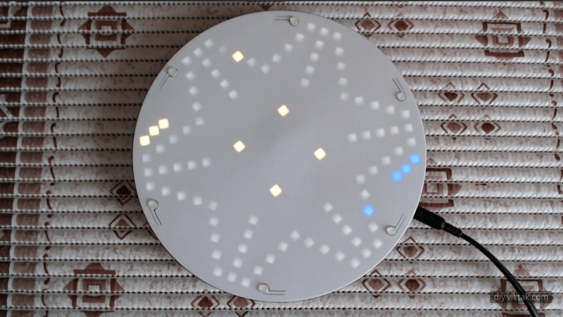
The new game board is built inside a stylish 3D-printed enclosure with a thin white front face, under which the 115 LEDs sit. Seven LEDs in the center represent a die, and the rest mark out the track around the board and each user’s home row. Up to six people can play on the board, and different colors of the LEDs along the track represent their tokens’ positions. To prevent light leaks, a black plastic barrier surrounds each LED. Each player has one button to control their pieces, with a combination of long and short presses serving to select one of the possible actions.

The electronics themselves are mounted on seven circuit boards, which were divided into sections to reduce their size and therefore their manufacturing cost. For component placement reasons, [Viktor] used a barrel connector instead of USB, but for more general compatibility also created an adapter from USB-C to a barrel plug. The board is controlled by an ESP32-S3, which hosts a server that can be used to set game rules, configure player colors, save and load games, and view statistics for the game (who rolled the most sixes, who sent other players home most often, etc.).

If you prefer your games a bit more complex, we’ve also seen electronics added to Settlers of Catan. On a rather larger scale, there is also this LED-based board game which invites humans onto the board itself.

Thanks to [Victoria Bei] for the tip!

Building a Microscope without Lenses

A mirrorless camera is mounted on a stand, facing downwards toward a rotating microscope stage made of wood. A pair of wires come down from the stage, and a man's hand is pointing to the stage.

It’s relatively easy to understand how optical microscopes work at low magnifications: one lens magnifies an image, the next magnifies the already-magnified image, and so on until it reaches the eye or sensor. At high magnifications, however, that model starts to fail when the feature size of the specimen nears the optical system’s diffraction limit. In a recent video, [xoreaxeax] built a simple microscope, then designed another microscope to overcome the diffraction limit without lenses or mirrors (the video is in German, but with automatic English subtitles).

The first part of the video goes over how lenses work and how they can be combined to magnify images. The first microscope was made out of camera lenses, and could resolve onion cells. The shorter the focal length of the objective lens, the stronger the magnification is, and a spherical lens gives the shortest focal length. [xoreaxeax] therefore made one by melting a bit of soda-lime glass with a torch. The picture it gave was indistinct, but highly magnified.

A roughly rectangular red pattern is shown, with brighter streaks converging toward the center.
A cross section of the diffraction pattern of a laser diode shining through a pinhole, built up from images at different focal distances.

Besides the dodgy lens quality given by melting a shard of glass, at such high magnification some of the indistinctness was caused by the specimen acting as a diffraction grating and directing some light away from the objective lens. [xoreaxeax] visualized this by taking a series of pictures of a laser shining through a pinhole at different focal lengths, thus getting cross sections of the light field emanating from the pinhole. When repeating the procedure with a section of onion skin, it became apparent that diffraction was strongly scattering the light, which meant that some light was being diffracted out of the lens’s field of view, causing detail to be lost.

To recover the lost details, [xoreaxeax] eliminated the lenses and simply captured the interference pattern produced by passing light through the sample, then wrote a ptychography algorithm to reconstruct the original structure from the interference pattern. This required many images of the subject under different lighting conditions, which a rotating illumination stage provided. The algorithm was eventually able to recover a sort of image of the onion cells, but it was less than distinct. The fact that the lens-free setup was able to produce any image at all is nonetheless impressive.

To see another approach to ptychography, check out [Ben Krasnow’s] approach to increasing microscope resolution. With an electron microscope, ptychography can even image individual atoms.

Measuring Earth’s Rotation with Two Gyroscopes

A 3D-printed assembly standing on short legs is visible. A portion extends upward with the word "Nord" sunk into it. Cables extend from one side of the upright portion, and a side view of a circuit board is visible at the front of the assembly.

We’ve probably all had a few conversations with people who hold eccentric scientific ideas, and most of the time they yield nothing more than frustration and perhaps a headache. In [Bertrand Selva]’s case, however, a conversation with a flat-earth believer yielded a device that uses a pair of gyroscopes to detect earth’s rotation, demonstrating that rotation exists without the bulkiness of a Foucalt pendulum.

[Bertrand] built his apparatus around a pair of BMI160 MEMS gyroscopes, which have a least significant bit for angular velocity corresponding to 0.0038 degrees per second, while the earth rotates at 0.00416 degrees per second. To extract such a small signal from all the noise in the measurements, the device makes measurements with the sensors in four different positions to detect and eliminate the bias of the sensors and the influence of the gravitational field. Before running a test, [Bertrand] oriented the sensors toward true north, then had a stepper motor cycle the sensors through the four positions, while a Raspberry Pi Pico records 128 measurements at each position. It might run the cycle as many as 200 times, with error tending to decrease as the number of cycles increases.

A Kalman filter processes the raw data and extracts the signal, which came within two percent of the true rotational velocity. [Bertrand] found that the accuracy was strongly dependent on how well the system was aligned to true north. Indeed, the alignment effect was so strong that he could use it as a compass.

In the end, the system didn’t convince [Bertrand]’s neighbor, but it’s an impressive demonstration nonetheless. This system is a bit simpler, but it’s also possible to measure the earth’s rotation using a PlayStation. For higher precision, check out how the standards organizations manage these measurements.

Building an Acoustic Radiometer

A circular metal vessel is shown, with a symmetrical rotor of four vanes standing inside. At the bottom of the vessel are four loudspeakers.

A Crookes radiometer, despite what many explanations claim, does not work because of radiation pressure. When light strikes the vanes inside the near-vacuum chamber, it heats the vanes, which then impart some extra energy to gas molecules bouncing off of them, causing the vanes to be pushed in the opposite direction. On the other hand, however, it is possible to build a radiometer that spins because of radiation pressure differences, but it’s easier to use acoustic radiation than light.

[Ben Krasnow] built two sets of vanes out of laser-cut aluminium with sound-absorbing foam attached to one side, and mounted the vanes around a jewel bearing taken from an analog voltmeter. He positioned the rotor above four speakers in an acoustically well-sealed chamber, then played 130-decibel white noise on the speakers. The aluminium side of the vanes, which reflected more sound, experienced more pressure than the foam side, causing them to spin. [Ben] tested both sets of vanes, which had the foam mounted on opposite sides, and they spun in opposite directions, which suggests that the pressure difference really was causing them to spin, and not some acoustic streaming effect.

The process of creating such loud sounds burned out a number of speakers, so to prevent this, [Ben] monitored the temperature of a speaker coil at varying amounts of power. He realized that the resistance of the coil increased as it heated up, so by measuring its resistance, he could calculate the coil’s temperature and keep it from getting too hot. [Ben] also tested the radiometer’s performance when the chamber contained other gasses, including hydrogen, helium, carbon dioxide, and sulfur hexafluoride, but none worked as well as air did. It’s a bit counterintuitive that none of these widely-varying gasses worked better than air did, but it makes sense when one considers that speakers are designed to efficiently transfer energy to air.

It’s far from an efficient way to convert electrical power into motion, but we’ve also seen several engines powered by acoustic resonance. If you’d like to hear more about the original Crookes radiometers, [Ben]’s also explained those before.

Watching Radioactive Decay with a Homemade Spinthariscope

A microscope objective is sitting on a spool of solder in a metal tin, in front of a circuit board which has wires running away from it.

Among the many science toys that have fallen out of fashion since we started getting nervous around things like mercury, chlorinated hydrocarbons, and radiation is the spinthariscope, which let people watch the flashes of light on a phosphor screen as a radioactive material decayed behind it. In fact, they hardly expose their viewers to any radiation, which makes [stoppi]’s homemade spinthariscope much safer than it might first seem.

[Stoppi] built the spinthariscope out of the eyepiece of a telescope, a silver-doped zinc sulfide phosphor screen, and the americium-241 capsule from a smoke detector. A bit of epoxy holds the phosphor screen in the lens’s focal plane, and the americium capsule is mounted on a light filter and screwed onto the eyepiece. Since americium is mainly an alpha emitter, almost all of the radiation is contained within the device.

After sitting in a dark room for a few minutes to let one’s eyes adjust, it’s possible to see small flashes of light as alpha particles hit the phosphor screen. The flashes were too faint for a smartphone camera to pick up, so [stoppi] mounted it in a light-tight metal box with a photomultiplier and viewed the signal on an oscilloscope, which revealed many small pulses.

While a spinthariscope is a bit easier to set up, they’re considerably less common among amateurs than are cloud chambers, another way to view radioactive decay. For scientific instruments, though, this project’s scintillator-and-photomultiplier approach is the standard, from tiny gamma ray spectrometers to giant neutrino detectors.

(Neural) Networking with a Business Card

A circuit board in the shape of a business card is shown. The circuitry is confined to the left side of the board, and the rest is used for text.

A PCB business card is a great way for electrical engineers to impress employers with their design skills, but the software they run can be just as impressive as the card itself. As a programmer with an interest in embedded machine learning, [Dave McKinnon] wanted a card that showcased his skills, so he designed oneΒ that runs voice recognition.

[Dave] specifically wanted to run a neural network on his card, but needed to make it small enough to run on a microcontroller. Voice recognition looked like a good fit for this, since audio can be represented with relatively little data, a microphone is cheap and easy to add to a circuit board, and there was already an example of someone running such a voice recognition network on an Arduino. To fit the neural network into 46 kB, it only distinguishes the words β€œone” through β€œnine,” and displays its guess on an LED seven-segment display. [Dave] first prototyped the system with an Arduino, then designed the circuit board around an RP2040.

The switch from Arduino to the RP2040 brought with it a mysterious change: it would usually recognize the word β€œeight,” but none of the other numbers. After much investigation, it turned out that the new circuit was presenting samples at a much higher rate than the older one had, which was throwing the network off. [Dave] increased the sampling period and had the user speak the numbers slowly, which solved the issue.

The microcontroller was well chosen; the RP2040 is good enough for machine learning that there are dev boards explicitly designed for it, and even comparatively less powerfulΒ Arduino boards can do surprisingly good voice recognition. On the hardware side, [Dave] citedΒ some of the Linux business cards we’ve seen as inspiration.

❌