Reading view

There are new articles available, click to refresh the page.

3D Printering: That New Color Printer

Art of 3D printer in the middle of printing a Hackaday Jolly Wrencher logo

Color 3D printing has gone mainstream, and we expect more than one hacker will be unpacking one over the holidays. If you have, say, a color inkjet printer, the process is simple: print. Sure, maybe make sure you tick the “color” box, but that’s about it. However, 3D printers are a bit more complicated.

There are two basic phases to printing color 3D prints. First, you have to find or make a model that has different colors. Even if you don’t make your own models (although you should), you can still color prints in your slicer.

The second task is to set the printer up to deal with those multiple colors. There are several different ways to do this, and each one has its pros and cons. Of course, some of this depends on your slicer, and some depends on your printer. For the purposes of this post, I’ll assume you are using a Slic3r fork like Prusa or OrcaSlicer. Most of the lower-priced printers these days work in roughly the same way.

Current State of Color

In theory, there are plenty of ways to 3D print in color. You can mix hot plastic in the nozzle or use multiple nozzles, each loaded with a different color. But most entry-level color printers use a variation of the same technique. Essentially, they are just like single-nozzle FDM printers, but they have three extra pieces. First, there is a sensor that can tell if filament is in the hot end or not. There’s also a blade above the hot end but below the extruder that can cut the filament off cleanly on command. This usually involves having the hot end ram some actuator that pushes the spring-loaded knife through the filament.

The third piece is some unit to manage moving a bunch of filaments in and out of the hot end. Everyone calls this something else. Bambu calls it an AMS while Flashforge calls it an IFS. Prusa has an MMU. Whatever you call it, it just moves cold filament around: either pushing it into the extruder or pulling it out.

Every filament change starts with cutting the filament below the extruder. That leaves the stringy melted part down in the nozzle. Then the extruder can pull the rest up until the management unit can take over and pull it totally out of the hot end/extruder assembly. That’s why there’s a sensor. It pulls until it sees that the extruder is empty or it times out and throws an error.

Then it is simple enough to move another filament back into the extruder. Of course, the first thing it has to do is push the leftover filament out of the nozzle. Most printers move to a bin and extrude until they are sure the color has changed. However,  there are other options.

Even if you push out all the old filament, you may want to print a little waste piece of the new filament before you start printing, and this is called a purge block. Slicers can also push purge material into places like your infill, for example. Some can even print objects with the purge, presumably an object that doesn’t have to look very nice. Depending on your slicer, printer, and workflow, you can opt to print without a purge block, which can work well when you have a part where each layer is a solid color. Some printers will let you skip the discharge step, too, which is often called “poop.”

One caveat, of course, is that all this switching logic takes time and generates waste. A good rule of thumb is to try to print many objects at one time if you are going to switch filament, because the changes are what take time and generate waste. Printing dozens of objects will generate essentially the same amount of waste as printing one. Of course, printing a dozen objects will take longer than a single one, but the biggest part of the time is filament changes, which doesn’t change no matter how many or few you print.

Get Ready to Print

Painting in Orca Slicer

We’ve talked before about creating your own color objects. We’ve even seen how to do it in TinkerCad. Of course, you can also load designs that already have color in them. However, there are several different ways to put color into an otherwise monochrome print.

First, you can take a regular print and use your slicer’s paint function to paint areas with different colors. That works, but it is often tedious, and for complex shapes, it is error-prone. Another downside is that you can’t really control the depth easily, so you get strange filament shifts inside the object if you do it that way.

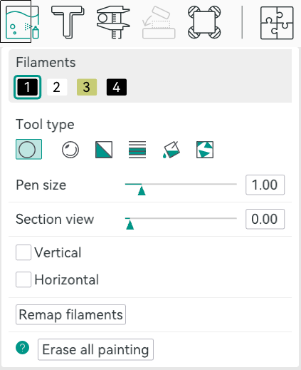
In Orca, you can select an object in the Prepare screen and then use N, or the toolbar, to bring up the paint color dialog. From there, you can pick a brush shape, pen size, and color. Then it is easy to just paint where you like by left-dragging. You can remove paint by pressing Shift while clicking or dragging. Press the little question mark at the bottom left to see other options.

Once you make a color print, the slicer will automatically place a purge block for you unless you turn it off. Assuming you use it, it is a good idea to drag it on the build plate to be closer to the print, which can shave a few minutes of travel time.

From Many, One

Possibly the easiest way, other than not printing in color, of course, is to have each part of the model that needs to be one color as a separate STL file, as we talked about in the previous post. You tell the slicer which part goes with which filament, and you are done.

In Orca, the best way to do this is to import several STL models at one time. The software will ask you: “Load these files as a single object with multiple parts?” If you agree, you get one object made of individual pieces.

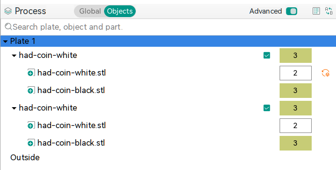
The resulting object won’t look much different until you go to “Process”, on the left-hand side of the screen, and switch from the default Global to Objects. From there, you’ll see the objects and their components. At first, each one will be set to the same color, but by clicking on the color box, you can assign different colors. In the screenshot, you’ll see two identical objects, each with two parts. Each part has a different color. The number is the extruder that holds that color.

Two filament changes are all it takes to make this nice-looking ornament

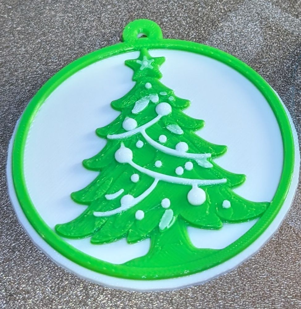
There is another way, though. You can avoid almost all of the waste generation and extra time if your model is designed so that each layer is a single color. People have done this for years, where you put a pause in your G-code and then switch filament manually. The idea is the same but the printer can switch for you. For example, the Christmas Tree ornament uses two filament changes to print white, then green, then white again. This works great for lettering and logos and other simple setups where you simply need some contrast.

In Orca, you’ll want to slice your model once and switch to the preview tab. Using the vertical slider on the right-hand side, adjust the view until it shows you where you want the filament change. Then right-click and select “Change Filament.” This is the same way you add a pause if you want to change filament manually, for example.

If you use this method, remember to turn off the purge block. You don’t really need it.

Summary

So now, when you unwrap that shiny new multimaterial printer, you have a plan. Get a color model or color one yourself. Then you can decide if you need color changes or full-blown, and waste-prone, color printing. Either way, have fun!

Retrotechtacular: Learning the Slide Rule the New Old Fashioned Way

Learning something on YouTube seems kind of modern. But if you are watching a 1957 instructional film about slide rules, it also seems old-fashioned. But Encyclopædia Britannica has a complete 30-minute training film, which, what it lacks in glitz, it makes up for in mathematical rigor.

We appreciated that it started out talking about numbers and significant figures instead of jumping right into the slide rule. One thing about the slide rule is that you have to sort of understand roughly what the answer is. So, on a rule, 2×3, 20×30, 20×3, and 0.2×300 are all the same operation.

You don’t actually get to the slide rule part for about seven minutes, but it is a good idea to watch the introductory part. The lecturer, [Dr. Havery E. White] shows a fifty-cent plastic rule and some larger ones, including a classroom demonstration model. We were a bit surprised that the prestigious Britannica wouldn’t have a bit better production values, but it is clear. Perhaps we are just spoiled by modern productions.

We love our slide rules. Maybe we are ready for the collapse of civilization and the need for advanced math with no computers. If you prefer reading something more modern, try this post. Our favorites, though, are the cylindrical ones that work the same, but have more digits.

MicroCAD Programs CAD

We love and hate OpenSCAD. As programmers, we like describing objects we want to 3D print or otherwise model. As programmers, we hate all the strange things about OpenSCAD that make it not like a normal programming language. Maybe µCAD (or Microcad) is the answer. This new entry in the field lets you build things programmatically and is written in Rust.

In fact, the only way to get it right now is to build it from source using cargo. Assuming you already have Rust, that’s not hard. Simply enter: cargo install microcad. If you don’t already have Rust, well, then that’s a problem. However, we did try to build it, and despite having the native library libmanifold available, Rust couldn’t find it. You might have better luck.

You can get a feel for the language by going through one of the tutorials, like the one for building a LEGO-like shape. Here’s a bit of code from that tutorial:


use std::geo2d::*;
use std::ops::*;

const SPACING = 8mm;

op grid(columns: Integer, rows: Integer) {
@input
.translate(x = [1..columns] * SPACING, y = [1..rows] * SPACING)
.align()
}

sketch Base(
columns: Integer,
rows: Integer,
width: Length,
height: Length
) {
thickness = 1.2mm;
frame = Frame(width, height, thickness);
struts = Ring(outer_d = 6.51mm, inner_d = 4.8mm)
.grid(columns = columns-1, rows = rows-1);
frame | struts;
}

There are proper functions, support for 2D sketches and 3D objects, and even a VSCode extension.

Will you try it? If we can get it to build, we will. Meanwhile, there’s always OpenSCAD. Even TinkerCAD can do some parametric modeling.

DIY Test Gear from 1981

We can’t get enough of [Bettina Neumryn’s] videos. If you haven’t seen her, she takes old electronics magazines, finds interesting projects, and builds them. If you remember these old projects, it is nostalgic, and if you don’t remember them, you can learn a lot about basic electronics and construction techniques. This installment (see below) is an Elektor digital voltmeter and frequency counter from late 1981.

As was common in those days, you could find the PCB layouts in the magazine. In this case, there were two boards. The schematic shows that a counter and display driver chip — a 74C928 — does most of the heavy lifting for the display and the counter.

It is easy to understand how the frequency counter works. You clip the input with a pair of diodes, amplify it a bit, square it with a Schmitt trigger, and then, possibly, prescale it using a divider. The voltmeter is a little trickier: it uses a voltage divider, an op amp, and a 555 to convert the voltage to a frequency.

Of course, finding the parts for an old project can be a challenge. A well-stocked junk drawer doesn’t hurt. A PCB etching setup helps, too.

We’ve looked at her magazine rebuilds before. If you ever get the urge to tackle a project like this, you can find all the grand old magazines online.

Citizen Science by the Skin of Your Teeth

If you are a schoolkid of the right age, you can’t wait to lose a baby tooth. In many cultures, there is a ritual surrounding it, like the tooth fairy, a mouse who trades your tooth for a gift, or burying the tooth somewhere significant. But in 1958, a husband and wife team of physicians wanted children’s teeth for a far different purpose: quantifying the effects of nuclear weapons testing on the human body.

A young citizen scientist (State Historical Society of Missouri)

Louise and Eric Reiss, along with some other scientists, worked with Saint Louis University and the Washington School of Dental Medicine to collect and study children’s discarded teeth. They were looking for strontium-90, a nasty byproduct of above-ground nuclear testing. Strontium is similar enough to calcium that consuming it in water and dairy products will leave the material in your bones, including your teeth.

The study took place in the St. Louis area, and the results helped convince John F. Kennedy to sign the Partial Nuclear Test Ban Treaty.

They hoped to gather 50,000 teeth in a year. By 1970, 12 years later, they had picked up over 320,000 donated teeth. While a few kids might have been driven by scientific altruism, it didn’t hurt that the program used colorful posters and promised each child a button to mark their participation.

Children’s teeth were particularly advantageous to use because they are growing and are known to readily absorb radioactive material, which can cause bone tumors.

Scale

A fair trade for an old tooth? (National Museum of American History)

You might wonder just how much nuclear material is floating around due to bombs. Obviously, there were two bombs set off during the war, as well as the test bombs required to get to that point. Between 1945 and 1980, there were five countries conducting atmospheric tests at thirteen sites. The US, accounting for about 65% of the tests, the USSR, the UK, France, and China detonated 504 nuclear devices equivalent to about 440 megatons of TNT.

Well over 500 bombs with incredible force have put a lot of radioactive material into the atmosphere. That doesn’t count, too, the underground tests that were not always completely contained. For example, there were two detonations in Mississippi where the radiation was contained until they drilled holes for instruments, leaving contaminated soil on the surface. Today, sites like this have “monuments” explaining that you shouldn’t dig in the area.

Of course, above-ground tests are worse, with fallout affecting “downwinders” or people who live downwind of the test site. There have been more than one case of people, unaware of the test, thinking the fallout particles were “hot snow” and playing in it. Test explosions have sent radioactive material into the stratosphere. This isn’t just a problem for people living near the test sites.

Results

By 1961, the team published results showing that strontium-90 levels in the teeth increased depending on when the child was born. Children born in 1963 had levels of strontium-90 fifty times higher than those born in 1950, when there was very little nuclear testing.

The results were part of the reason that President Kennedy agreed to an international partial test ban, as you can see in the Lincoln Presidential Foundation video below. You may find it amazing that people would plan trips to watch tests, and they were even televised.

In 2001, Washington University found 85,000 of the teeth stored away. This allowed the Radiation and Public Health Project to track 3,000 children who were, by now, adults, of course.

Sadly, 12 children who had died from cancer before age 50 had baby teeth with twice the levels of the teeth of people who were still alive at age 50. To be fair, the Nuclear Regulatory Commission has questioned these findings, saying the study is flawed and fails to account for other risk factors.

And teeth don’t just store strontium. In the 1970s, other researchers used baby teeth to track lead ingestion levels. Baby teeth have also played a role in the Flint Water scandal. In South Africa, the Tooth Fairy Project monitored heavy metal pollution in children’s teeth, too.

Teeth aren’t the only indicator of nuclear contamination. Steel is also at risk.

Featured image: “Castle Bravo Blast” by United States Department of Energy.

Heater is Either a Miracle or a Scam

[Big Clive] picked up a tiny heater for less than £8 from the usual sources. Would you be shocked to learn that its heating capacity wasn’t as advertised? No, we weren’t either. But [Clive] treats us to his usual fun teardown and analysis in the video below.

A simple test shows that the heater drew about 800 W for a moment and drops as it heats until it stabilizes at about 300 W. Despite that, these units are often touted as 800 W heaters with claims of heating up an entire house in minutes. Inside are a fan, a ceramic heater, and two PCBs.

The ceramic heaters are dwarfed by metal fins used as a heat exchanger. The display uses a clever series of touch sensors to save money on switches. The other board is what actually does the work.

[Clive] was, overall, impressed with the PCB. A triac runs the heaters and the fan. It also includes a thermistor for reading the temperature.

You can learn more about the power supply and how the heater measures up in the video. Suffice it to say, that a cheap heater acts like a cheap heater, although as cheap heaters go, this one is built well enough.

Water on Mars? Maybe Not

We were as excited as anyone when MARSIS (the Mars Advanced Radar for Subsurface and Ionosphere Sounding) experiment announced there was possibly liquid water under the southern polar ice cap. If there is liquid water on Mars, it would make future exploration and colonization much more feasible. Unfortunately, SHARAD (the Shallow Radar) has a new trick that suggests the data may not indicate liquid water after all.

While the news is a bummer, the way scientists used SHARAD to confirm — or, in this case, deny — the water hypothesis was a worthy hack. The SHARAD antenna is on the Mars Reconnaissance Orbiter, but in a position that makes it difficult to obtain direct surface readings from Mars. To compensate, operators typically roll the spacecraft to give the omnidirectional antenna a clearer view of the ground. However, those rolls have been under 30 degrees.

Computer modelling indicated that rolls of 120 degrees would greatly improve the SHARAD data. So far, four of these “very large roll” or VLR maneuvers have allowed more detailed probes of the surface with SHARAD. Unfortunately the new data didn’t back up the early findings. Scientists now think the reflection may be just an unusually flat surface under the ice.

Of course, just because there might not be water in that location doesn’t mean there isn’t any at all. Want to live on Mars? There’s a lot to think about.

Ultrasonic Cutting on the Cheap

When you think of ultrasonics,  you probably think of a cleaner or maybe a toothbrush. If you are a Star Trek fan, maybe you think of knocking out crew members or showers. But there is another practical use of ultrasonics: cutting. By vibrating a blade at 40 kHz or so, you can get clean, precise cuts in a variety of materials. The problem? Commercial units are quite expensive. So [Electronoobs] decided to roll his own. Check it out in the video below.

There are dreams and then there’s reality. Originally, the plan was for a handheld unit, but this turned out not to be very practical. Coil actuators were too slow. Piezo elements made more sense, but to move the blade significantly, you need a larger element.

Taking apart an ultrasonic cleaner revealed a very large element, but mounting it to a small blade would be a problem. The next stop was an ultrasonic toothbrush. Inside was a dual piezo element with an interesting trick. The elements were mounted in a horn that acts like an ultrasonic megaphone, if you will.

These horns are available, and he found an off-the-shelf solution with four piezos and a large horn that seemed promising. Driving the elements, though, requires a 40 kHz 100 VAC signal. His original board didn’t work — but he’s not giving up. But, for now, he used a simple circuit on a breadboard. However, it didn’t make a strong vibration, even with a larger horn.

Comparison with ultrasonic cleaners showed that his output voltage wasn’t enough. The expedient answer was to buy an ultrasonic cleaner kit (who knew they came as kits?) and use the boards from it to drive the horn and the blade. That worked very well.

His current thinking is that the cleaner driver may be too large, since the blade and horn get hot in use. But he still encased it with a 3D printed case and wound up with a usable tool. His next version should be portable and maybe run a little cooler.

Ultrasonic sensors are, of course, super useful. Or you can always levitate tiny things with it.

Smelly Ultrasound

We aren’t sure why, but [Lev Chizhov] and some other researchers have found a way to make you smell things by hitting your head with ultrasound. Apparently, your sense of smell lives in your olfactory bulb, and no one, until now, has thought to try zapping it with ultrasound to see what happens.

The bulb is somewhere behind your nose, as you might expect. This is sub-optimal for ultrasound because your nose isn’t flat, and it is full of air. Packing a subject’s nose with gel wasn’t going to win many fans. The answer was to place the transducer on the person’s forehead and shoot down at the bulb. They made a custom headset that let them precisely target areas of the subject’s bulb guided by an MRI.

So far, they have a sample size of two, but they’ve managed to induce the smell of fresh air, garbage, ozone, and burning wood. What would you do with this? Smell-o-vision? A garbage truck VR game? Let us know in the comments. We don’t think this is exactly how the last VR smell gadget we saw worked, but — honestly — we aren’t completely sure.

Retrotechtacular: Computers in Schools? 1979 Says Yes

The BBC wanted to show everyone how a computer might be used in schools. A program aired in 1979 asks, “Will Computers Revolutionise Education?” There’s vintage hardware and an appearance of PILOT, made for computer instructions.

Using PILOT looks suspiciously like working with a modern chatbot without as much AI noise. The French teacher in the video likes that schoolboys were practicing their French verb conjugation on the computer instead of playing football.

If you want a better look at hardware, around the five-minute mark, you see schoolkids making printed circuit boards, and some truly vintage oscilloscope close-ups. There are plenty of tiny monitors and large, noisy printing terminals.

You have to wonder where the eight-year-olds who learned about computers in the video are today, and what kind of computer they have. They learned binary and the Towers of Hanoi. Their teacher said the kids now knew more about computers than their parents did.

As a future prediction, [James Bellini] did pretty well. Like many forecasters, he almost didn’t go far enough, as we look back almost 50 years. Sure, Prestel didn’t work out as well as they thought, dying in 1994. But he shouldn’t feel bad. Predicting the future is tough. Unless, of course,  you are [Arthur C. Clarke].

Assistive Radio Tells You What You Can’t See

We think of radios as audio devices, but for people who are visually impaired, it can be difficult to tell which channel you are listening to at any given time. [Sncarter] has a family member with vision impairment and built a radio to help her. Unfortunately, it was difficult to replicate, so he decided to try again. The result is an FM radio that provides audible status notifications about power and frequency. Check it out in the video below.

This isn’t just some hacked-up commercial radio, but a ground-up design that uses a TEA5767 with an ATMega328 for control. There is an LCD for when someone else might use the radio and an audio amplifier. He built the prototype on a breadboard, but moved the finished product to a PCB.

It isn’t just the electronics and the sound that are assistive. The case has raised bosses to help the user find things like the switch and rotary encoder. The Arduino can speak frequency announcements, although the quality of the voice is something he wants to tackle in the next revision.

These radios on a chip give you many design options. These same ideas can be useful for audiobook players, too.

How to Use That Slide Rule

You have that slide rule in the back of the closet. Maybe it was from your college days. Maybe it was your Dad’s. Honestly. Do you know how to use it? Really? All the scales? That’s what we thought. [Amen Zwa, Esq.] not only tells you how slide rules came about, but also how to use many of the common scales. You can also see his collection and notes on being a casual slide rule collector and even a few maintenance tips.

The idea behind these computing devices is devilishly simple. It is well known that you can reduce a multiplication operation to addition if you have a table of logarithms. You simply take the log of both operands and add them. Then you do a reverse lookup in the table to get the answer.

For a simple example, you know the (base 10) log of 10 is 1 and the log of 1000 is 3. Adding those gives you 4, and, what do you know, 104 is 10,000, the correct answer. That’s easy when you are working with numbers like 10 and 1000 with base 10 logarithms, but it works with any base and with any wacky numbers you want to multiply.

The slide rule is essentially a log table on a stick. That’s how the most common scales work, at least. Many rules have other scales, so you can quickly, say, square or cube numbers (or find roots). Some specialized rules have scales for things like computing power.

We collect slide rules, too. Even oddball ones. We’ve often said that the barrier of learning to use a slide rule weeded out many bad engineers early.

A Paper Caper: The Hole Data

Since the dawn of computers, we’ve tried different ways to store data. These days, you grab data over the network, but you probably remember using optical disks, floppies, or, more recently, flash drives to load something into your computer. Old computers had to use a variety of methods, such as magnetic tape. But many early computers used some technology that existed from the pre-computer era, like punched cards or, as [Anthony Francis-Jones] shows us, paper tape.

Paper tape was common in TeleType machines and some industrial applications. In fact, as early as 1725, looms could use paper tape, which would eventually lead to punched cards. For computers, there were two common variations that differed in how many holes were punched across the tape: 5 or 8. There was also a small sprocket hole that allowed a gear to move the tape forward through a reader.

Typically, brushes or optical sensors would read the holes into the computer. Some paper tape used regular paper, but others used oily paper. You could also get tapes made out of mylar, which was very durable.

The other big difference in tapes was in how they were punched. A conventional tape had the entire hole punched out, leaving confetti-like “chad.” There were also chadless tapes where the chad was left slightly connected to the paper.

One common feature of paper tape was that it would skip any section where every hole had been punched. This allowed you to erase parts of the tape by punching over it. Then, with scissors and tape, you could splice sections by lining up the fully punched areas between two sections of tape. You could also make endless loops of tape.

Paper tape was used as a crude word processor back in the day. They were even used to send wire photos.

Gilbert Cell Lacks Sullivan

If you’ve ever used an NE602 or similar IC to build a radio, you might have noticed that the datasheet has a “gilbert cell” mixer. What is that? [Electronics for the Inquisitive Experimenter] explains them in a recent video. The gilbert cell is a multiplier, and multiplying two waveforms will work to mix them together.

At the heart of the gilbert cell is essentially three differential amplifiers that share a common current source. The video shows LTSpice simulations of the circuits as he explains them.

One reason these work well on ICs is that they require very closely-matched transistors. In real life, it is hard to get transistors that match exactly. But when they are all on the same slab of silicon, it is fairly straightforward.

What we really like is that after simulating and explaining the circuit, he explains why multipliers mix signals, then builds a real circuit on the bench using discrete transistors and matched transistor arrays. There is a bit of trigonometry in the explanation, but nothing too difficult.

Of course, the most common application of differential amplifiers is the op amp. The NE602 is out of production, sadly, but if you can find any, they make dandy receivers.

Rare Filament Makes Weird Benchies

[Zack], in addition to being a snappy dresser, has a thing for strange 3D printing filament. How strange? Well, in a recent video, he looks at filaments that require 445 C. Even the build plate has to be super hot. He also looks at filament that seems like iron, one that makes you think it is rubber, and a bunch of others.

As you might expect, he’s not using a conventional 3D printer. Although you might be able to get your more conventional printer to handle some of these, especially with some hacking. There is filament with carbon fiber, glass fiber, and more exotic add-ons.

Most of the filaments need special code to get everything working. While you might think you can’t print these engineering filaments, it stands to reason that hobby-grade printers are going to get better over time (as they already have). If the day is coming when folks will be able to print any of these on their out-of-the-box printer, we might as well start researching them now.

If you fancy a drinking game, have a shot every time he changes shots and a double when the Hackaday Prize T-shirt shows up.

Pong Gets the Boot

You might be surprised to find out that [Akshat Joshi’s] Pong game that fits in a 512-byte boot sector isn’t the first of its kind. But that doesn’t mean it isn’t an accomplishment to shoehorn useful code in that little bitty space.

As you might expect, a game like this uses assembly language. It also can’t use any libraries or operating system functions because there aren’t any at that particular time of the computer startup sequence. Once you remember that the bootloader has to end with two magic bytes (0x55 0xAA), you know you have to get it all done in 510 bytes or less.

This version of Pong uses 80×25 text mode and writes straight into video memory. You can find the code in a single file on GitHub. In the old days, getting something like this working was painful because you had little choice but reboot your computer to test it and hope it went well. Now you can run it in a virtual machine like QEMU and even use that to debug problems in ways that would have made a developer from the 1990s offer up their life savings.

We’ve seen this before, but we still appreciate the challenge. We wonder if you could write Pong in BootBasic?

Hackers Can’t Spend a Penny

We aren’t here to praise the penny, but rather, to bury it. The penny, and its counterparts, have been vanishing all around the world as the cost of minting one far outweighs its value. But hackers had already lost a big asset: real copper pennies, and now even the cheaply made ones are doomed to extinction.

If you check your pockets and find a pre-1982 penny, it’s almost all copper. Well, 95% of its slightly-more-than-3-gram heft is pure copper. Since then, the copper penny’s been a fraud, weighing 2.5 g and containing only a 2.5% copper plate over a zinc core. During WWII, they did make some oddball steel pennies, but that was just a temporary measure.

Penny Science

If you are a certain age, you might remember building a “voltaic pile.” These primitive batteries use pennies, cardboard soaked in vinegar, and aluminum foil. Granted, it wasn’t very practical, so raiding your couch for change to make a battery was never really practical, but it was a fun science experiment. There are dozens of YouTube videos showing this popular experiment, including the [ScienceBuddies] video below.

Old pennies were also a cheap and easy source of copper. Vinegar or lemon juice and some voltage made it simple to copperplate another metal object, like a nail. Copper also makes a good heatsink. We’ve seen Raspberry Pis and similar boards with heatsinks that cost an integer number of pennies, because that’s all they were. An oxidized penny shows up in some foxhole radios. They were also handy little weights if you made a balance or for taming a wobbly ceiling fan.

If you were a real kid chemist, you might have done the classic trick of turning a penny into “silver” and then “gold.” You used not-so-lovely-to-handle sodium hydroxide, some zinc, and a flame to actually convert the penny to brass. It wasn’t really a precious metal, but still a good trick if you were a kid with a chemistry set. As the video from [Simon] below shows, that will still work with the copperplate pennies.

New Pennies

Not that you can’t have fun with zinc pennies. If you scratch the plating a bit and dip it in HCL, the zinc core fizzes away. What’s left is a hollow copper penny. If you don’t like using HCL, we hear you can do it over a stove and simply melt the zinc. We wouldn’t try either one of those without a vent hood and an unhealthy disregard for your personal safety, so, you know, don’t do that. But know that you could. [Craig] shows how to remove the zinc or the copper in the video below.

The legality of all this has always been a little suspect. Since 2006, it has been illegal to melt down coins for their metal value. Technically, using it in a science class probably won’t bring the Treasury agents swooping into your classroom, but you have been warned.

Household Hacker

Of course, it is going to take some time for all the pennies to really vanish. There are plenty of them, and you can still get around a hundred for a buck. But when they are gone, what other household items are easy to hack for science? Aluminum foil, maybe? Tell us your favorite in the comments.

Whether they were copper slugs or thinly plated zinc tokens, pennies were a weirdly perfect hacker material: cheap, conductive, sacrificial, and everywhere. We’ll miss them.

Featured image: “wealth of pennies” by [Reza]

Tech in Plain Sight: Pneumatic Tubes

Today, if you can find a pneumatic tube system at all, it is likely at a bank drive-through. A conversation in the Hackaday bunker revealed something a bit surprising. Apparently, in some parts of the United States, these have totally disappeared. In other areas, they are not as prevalent as they once were, but are still hanging in there. If you haven’t seen one, the idea is simple: you put things like money or documents into a capsule, put the capsule in a tube, and push a button. Compressed air shoots the capsule to the other end of the tube, where someone can reverse the process to send you something back.

These used to be a common sight in large offices and department stores that needed to send original documents around, and you still see them in some other odd places, like hospitals or pharmacy drive-throughs, where they may move drugs or lab samples, as well as documents. In Munich, for example, a hospital has a system with 200 stations and 1,300 capsules,  also known as carriers. Another medical center in Rotterdam moves 400 carriers an hour through a 16-kilometer network of tubes. However, most systems are much smaller, but they still work on the same principle.

That Blows — Or Sucks?

Air pressure can push a carrier through a tube or suck it through the tube. Depending on the pressure, the carrier can accelerate or decelerate. Large systems like the 12-mile and 23-mile systems at Mayo Clinic, shown in the video below, have inbound pipes, an “exchanger” which is basically a switchboard, and outbound pipes. Computers control the system to move the carriers at about 19 miles per hour.  You’ll see in the video that some systems use oval tubes to prevent the tubes from spinning inside the pipes, which is apparently a bad thing to do to blood samples.

In general, carriers going up will move via compressed air. Downward motion is usually via suction. If the carrier has to go in a horizontal direction, it could be either. An air diverter works with the blower to provide the correct pressures.

History

This seems a bit retro, but maybe like something from the 1950s. Turns out, it is much older than that. The basic system was the idea of William Murdoch in 1799. Crude pipelines carried telegram messages to nearby buildings. It is interesting, too, that Hero understood that air could move things as early as the first century.

In 1810, George Medhurst had plans for a pneumatic tube system. He posited that at 40 PSI — just a bit more than double normal sea-level air pressure — air would move at about 1,600 km/h. He felt that even propelling a load, it could attain a speed of 160 km/h. He died in 1827, though, with no actual model built.

In 1853, Josiah Latimer Clark installed a 200-meter system between the London Stock Exchange and the telegraph office. The telegraph operator would sell stock price data to subscribers — another thing that you’d think was more modern but isn’t.

Within a few years, the arrangement was common around other stock exchanges. By 1870, improvements enabled faster operation and the simultaneous transit of multiple carriers. London alone had 34 kilometers of tube by 1880. In Aberdeen, a tube system even carried fish from the market to the post office.

There were improvements, of course. Some systems used rings that could dial in a destination address, mechanically selecting a path through the exchange, which you can see one in the Mayo Clinic video. But even today, the systems work essentially the way they did in the 1800s.

Famous Systems

Several cities had pneumatic mail service. Paris ran a 467 km system until 1984. Prague’s 60 km network was in operation until 2002. Berlin’s system covered 400 km in 1940. The US had its share, too. NASA’s mission control center used tubes to send printouts from the lower floors up to the mission control room floor. The CIA Headquarters had a system running until 1989.

In 1920 Berlin, you could use the system as the equivalent of text messaging if you saw someone who caught your eye at one local bar. You could even send them a token of your affection, all via tube.

Mail by tube in 1863 (public domain; Illustrated London News)

In 1812, there was some consideration of moving people using this kind of system, and there were short-lived attempts in Ireland, London, and Paris, among other places, in the mid-1800s. In general, this is known as an “atmospheric railroad.”

As a stunt, in 1865, the London Pneumatic Despatch Company sent the Duke of Buckingham and some others on a five-minute trip through a pneumatic tube. The system was made to carry parcels at 60 km/h using a 6.4-meter fan run by a steam engine. The capsules, in this case, looked somewhat like an automobile. There are no reports of how the Duke and his companions enjoyed the trip.

A controller for the Prague mail system that operated until 2002 (public domain).

A 550-meter demonstration pneumatic train showed up at the Crystal Palace in 1864. Designed by Thomas Webster Rammell. It only operated for two months. A 6.7-meter fan blew air one way for the outbound trip and sucked it back for the return.

Don’t think the United States wasn’t in on all this, too. New York may be famous for its subway system, but its early predecessor was, in fact, pneumatic, as you can see in the video below.

Image from 1867 of the atmospheric train at Saint Germain (public domain).

Many of these atmospheric trains didn’t put the passengers in the capsule, but used the capsule to move a railcar. The Paris St. Germain system, which opened in 1837, used this idea.

Modern Times

Of course, where you once would send documents via tube, you’d now send a PDF file. Today, you mainly see tubes where it is important for an actual item to arrive quickly somewhere: an original document, cash, or medical samples. ThyssenKrupp uses a tube system to send toasty 900 °C steel samples from a furnace to a laboratory. Can’t do that over Ethernet.

There have been attempts to send food over tubes and even take away garbage. Some factories use them to move materials, too. So pneumatic tubes aren’t going away, even if they aren’t as common as they once were. In fact, we hear they are even more popular than ever in hospitals, so these aren’t just old systems still in use.

We haven’t seen many DIY pneumatic tube systems that were serious (we won’t count sucking Skittles through a tube with a shop vac). But we do see it in some robot projects. What would you do with a system like this? Even more importantly, are these still common in your area or a rarity? Let us know in the comments.

The King of Rocket Photography

If you are a nerdy kid today, you have your choice of wondrous gadgets and time wasters. When we were nerdy kids, our options were somewhat limited: there was ham radio, or you could blow things up with a chemistry set. There were also model rockets. Not only were model rockets undeniably cool, but thanks to a company called Estes, you could find ready-to-go kits and gear that made it possible to launch something into the heavens, relatively speaking. But what about photographic proof? No live streams or digital cameras. But there was the Estes AstroCam 100. [Bill Engar] remembers the joy of getting film from your rocket developed.

Of course, photography was another nerdy kid staple, so maybe you did your own darkroom work. Either way, the Astrocam 110 was a big improvement over the company’s earlier Camroc. In 1965, if you wanted to fly Camroc, you had to cut a 1.5-inch piece of film in a darkroom and mount it just to get one terrible black-and-white photo. Or, you could buy the film canisters loaded if you had the extra money, which, of course, you didn’t.

You might think it would be easy to strap a consumer-grade camera to a model rocket. The problem is, the rocket is moving fast. A regular camera of the era would give you a nicely exposed blur, but that’s about it. You had to send your little 1.5-inch film to Estes, who would use special processing methods to account for the fast shutter speed.

By 1979, the company came out with the Astrocam, and it took a standard but small 110 film cartridge. This gave you lower resolution, but was easy to shoot, easy to develop, and — even better — in grainy ASA 400 color. By 1993, the camera had upgrades and could use 200-speed film.

[Bill] treats us to plenty of pictures of his boyhood neighborhood. He also mentions that you can still get 110 film if you look for it, so if you pick up a camera on eBay, you could still fly it. Or, 3D print the latest from Estes. If you want to mount some serious cameras, maybe try liquid fuel.

An AI By Any Other Name

While there are many AI programs these days, they don’t all work in the same way. Most large language model “chatbots” generate text by taking input tokens and predicting the next token of the sequence. However, image generators like Stable Diffusion use a different approach. The method is, unsurprisingly, called diffusion. How does it work? [Nathan Barry] wants to show you, using a tiny demo called tiny-diffusion you can try yourself. It generates — sort of — Shakespeare.

For Stable Diffusion, training begins with an image and an associated prompt. Then the training system repeatedly adds noise and learns how the image degenerates step-by-step to noise. At generation time, the model starts with noise and reverses the process, and an image comes out. This is a bit simplified, but since something like Stable Diffusion deals with millions of pixels and huge data sets, it can be hard to train and visualize its operation.

The beauty of tiny-diffusion is that it works on characters, so you can actually see what the denoising process is doing. It is small enough to run locally, if you consider 10.7 million parameters small. It is pretrained on Tiny Shakespeare, so what comes out is somewhat Shakespearean.

The default training reportedly took about 30 minutes on four NVIDIA A100s. You can retrain the model if you like and presumably use other datasets. What’s interesting is that you can visualize the journey the text takes from noise to prose right on the terminal.

Want to dive deeper into diffusion? We can help. Our favorite way to prompt for images is with music.

❌