In case you didn’t hear — on October 22, 2025, the Internet Archive, who host the Wayback Machine at archive.org, celebrated a milestone: one trillion web pages archived, for posterity.
Founded in 1996 by Brewster Kahle the organization and its facilities grew through the late nineties; in 2001 access to their archive was greatly improved by the introduction of the Wayback Machine. From their own website on Oct 21 2009 they explained their mission and purpose:
Most societies place importance on preserving artifacts of their culture and heritage. Without such artifacts, civilization has no memory and no mechanism to learn from its successes and failures. Our culture now produces more and more artifacts in digital form. The Archive’s mission is to help preserve those artifacts and create an Internet library for researchers, historians, and scholars.
We were curious about the Internet Archive technology. Storing a copy (in fact two copies!) of the internet is no mean feat, so we did some digging to find out how it’s done. The best information available is in this article from 2016: 20,000 Hard Drives on a Mission. They keep two copies of every “item”, which are stored in Linux directories. In 2016 they had over 30 petabytes of content and were ingesting at a rate of 13 to 15 terabytes per day, web, and television being the most voluminous.
In 2016 they had around 20,000 individual disk drives, each housed in specialized computers called “datanodes”. The datanodes have 36 data drives plus two operating system drives per machine. Datanodes are organized into racks of 10 machines, having 360 data drives per rack. These racks are interconnected via high-speed Ethernet to form a storage cluster.
Even though content storage tripled over 2012 to 2016, the count of disk drives stayed about the same; this is because of disk drive technology improvements. Datanodes that were once populated with 36 individual 2 terabyte drives are today filled with 8 terabyte drives, moving single node capacity from 72 terabytes (64.8 T formatted) to 288 terabytes (259.2 T formatted) in the same physical space. The evolution of disk density did not happen in a single step, so there are populations of 2, 3, 4, and 8 T drives in the storage clusters.
We will leave you with the visual styling of Hackaday Beta in 2004, and what an early google.com or amazon.com looked like back in the day. Super big shout out to the Internet Archive, thanks for providing such an invaluable service to our community, and congratulations on this excellent achievement.
![[Piers] explains his code](https://hackaday.com/wp-content/uploads/2025/11/One-ROM-PIO-banner.jpg?w=800)
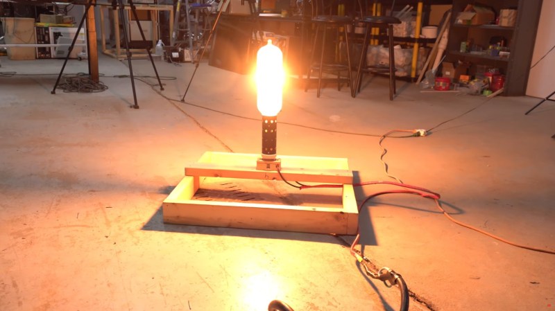
![[Usagi Electric] brandishing his raygun](https://hackaday.com/wp-content/uploads/2025/11/Usagi-Electric-Raygun-banner.jpg?w=800)

![Photo of [DENKI OTAKU] with his test circuit and oscilloscope](https://hackaday.com/wp-content/uploads/2025/11/TO-247-4-banner.jpg?w=800)
![[Usagi Electric] and his home brew computer](https://hackaday.com/wp-content/uploads/2025/11/TMS9900-home-brew-banner.jpg?w=800)