❌

Reading view

There are new articles available, click to refresh the page.

U.S. approves upgrade of Ukraine’s Patriot launchers

The U.S. State Department has approved a potential $105 million Foreign Military Sale to Ukraine for the modernization and sustainment of its Patriot air defense systems, according to a notification released by the Defense Security Cooperation Agency (DSCA). The proposed sale includes an upgrade of Ukraine’s current M901 launchers to the newer M903 configuration, enabling […]

If It Ain’t Broke… Add Something to It

Given that we live in the proverbial glass house, we can’t throw stones at [ellis.codes] for modifying a perfectly fine Vornado fan. He’d picked that fan in the first place because, unlike most fans, it had a DC motor. Of course, DC motors are easier to control with a microcontroller, and next thing you know, it was sporting an ESP32 and a WiFi interface.

The original fan was surprisingly sparse inside. A power supply, of course, and just a tiny PCB for a speed control. Oddly, it looks like the speed control was just a potentiometer and a 24 V supply. It wasn’t clear if the β€œmotor” had some circuitry in it to do PWM control or not. That seems likely, though.

Regardless, the project opted for a digital pot IC to maintain compatibility. One nice thing about the modification is that it replaces the existing board with the same connectors. So if you wanted to revert the fan to normal, you simply have to swap the boards back.

Now the fan talks to home automation software. Luckily, there’s still nothing wrong with it. We love seeing bespoke ESPHome projects. Even if your fan has WiFi, you might not like it communicating with Big Brother.

Monitoring an MQTT Broker: Why and How

Let's sayΒ you have several hundred IoT devices publishing telemetry data to your MQTT broker and things have been working smoothly for months. One morning you notice half of the sensor readings have stopped arriving. Your monitoring dashboard becomes a black hole, your automation stops working, and you can't determine whether the problem is with the devices, the network, or the MQTT broker.

Solar Project Update

A few months ago I wrote about my experimentation this year with solar power. I thought I would give a couple of updates.

The basic architecture hasn't changed, but some of the components have:


Given that I've never done this before, I expected to have some problems. However, I didn't expect every problem to be related to the power inverter. The inverter converts the 12V DC battery's power to 120V AC for the servers to use. Due to technical issues (none of which were my fault), I'm currently on my fourth power inverter.

Inverter Problem #1: "I'm Bond, N-G Bond"

The first inverter that I purchased was a Renogy 2000W Pure Sine Wave Inverter.


This inverter worked fine when I was only using the battery. However, if I plugged it into the automated transfer switch (ATS), it immediately tripped the wall outlet's circuit breaker. The problem was an undocumented grounding loop. Specifically, the three-prong outlets used in the United States are "hot", "neutral", and "ground". For safety, the neutral and ground should be tied together at one location; it's called a neutral-ground bond, or N-G bond. (For building wiring, the N-G bond is in your home or office breaker box.) Every outlet should only have one N-G bond. If you have two N-G bonds, then you have a grounding loop and an electrocution hazard. (A circuit breaker should detect this and trip immediately.)

The opposite of a N-G bond is a "floating neutral". Only use a floating neutral if some other part of the circuit has the N-G bond. In my case, the automated transfer switch (AFS) connects to the inverter and the utility/wall outlet. The wall outlet connects to the breaker box where the N-G bond is located.

What wasn't mentioned anywhere on the Amazon product page or Renogy web site is that this inverter has a built-in N-G bond. It will work great if you only use it with a battery, but it cannot be used with an ATS or utility/shore power.

There are some YouTube videos that show people opening the inverter, disabling the N-G bond, and disabling the "unsafe alarm". I'm not linking to any of those videos because overriding a safety mechanism for high voltage is incredibly stoopid.

Instead, I spoke to Renogy's customer support. They recommended a different inverter that has an N-G bond switch: you can choose to safely enable or disable the N-G bond. I contacted Amazon since it was just past the 30-day return period. Amazon allowed the return with the condition that I also ordered the correct one. No problem.

The big lesson here: Before buying an inverter, ask if it has a N-G bond, a floating neutral, or a way to toggle between them. Most inverters don't make this detail easy to find. (If you can't find it, then don't buy the inverter.) Make sure the configuration is correct for your environment.
  • If you ever plan to connect the inverter to an ATS that switches between the inverter and wall/utility/shore power, then you need an inverter that supports a floating neutral.

  • If you only plan to connect the inverter to a DC power source, like a battery or generator, then you need an inverter that has a built-in N-G bond.

Inverter Problem #2: It's Wrong Because It Hertz

The second inverter had a built-in switch to enable and disable the N-G bond. The good news it that, with the N-G bond disabled, it worked correctly through the ATS. To toggle the ATS, I put a Shelly Plug smart outlet between the utility/wall outlet and the ATS.


I built my own controller and it tracks the battery charge level. When the battery is charged enough, the controller tells the inverter to turn on and then remotely tells the Shelly Plug to turn off the wall outlet. That causes the ATS to switch over to the inverter.

Keep in mind, the inverter has it's own built-in transfer switch. However, the documentation doesn't mention that it is "utility/shore priority". That is, when the wall outlet has power, the inverter will use the utility power instead of the battery. It has no option to be plugged into a working outlet and to use the battery power instead of the outlet's power. So, I didn't use their built-in transfer switch.

This configuration worked great for about two weeks. That's when I heard a lot of beeping coming from the computer rack. The inverter was on and the wall outlet was off (good), but the Tripp Lite UPS feeding the equipment was screaming about a generic "bad power" problem. I manually toggled the inverter off and on. It came up again and the UPS was happy. (Very odd.)

I started to see this "bad power" issue about 25% of the time when the inverter turned on. I ended up installing the Renogy app to monitor the inverter over the built-in Bluetooth. That's when I saw the problem. The inverter has a frequency switch: 50Hz or 60Hz. The switch was in the 60Hz setting, but sometimes the inverter was starting up at 50Hz. This is bad, like, "fire hazard" bad, and I'm glad that the UPS detected and prevented the problem. Some of my screenshots from the app even showed it starting up low, like at 53-58 Hz, and then falling back to 50Hz a few seconds later.


(In this screenshot, the inverter started up at 53.9Hz. After about 15 seconds, it dropped down to 50Hz.)

I eventually added Bluetooth support to my homemade controller so that I could monitor and log the inverter's output voltage and frequency. The controller would start up the inverter and wait for the built-in Bluetooth to come online. Then it would read the status and make sure it was at 60Hz (+/- 0.5Hz) and 120V (+/- 6V) before turning off the utility and transferring the load to the inverter. If it came up at the wrong Hz, the controller would shut down the inverter for a minute before trying again.

It took some back-and-forth discussions with the Renogy technical support before they decided that it was a defect. They offered me a warranty-exchange. It took about two weeks for the inverter to be exchanged (one week there, one week back). The entire discussion and replacement took a month.

The replacement inverter was the same make and model. It worked great for the first two weeks, then developed the exact same problem! But rather than happening 25% of the time, it was happening about 10% of the time. To me, this looks like either a design flaw or a faulty component that impacts the entire product line. The folks at Renogy provided me with a warranty return and full refund.

If you read the Amazon reviews for the 2000W and 3000W models, they have a lot of 1-star reviews with comments about various defects. Other forums mention that items plugged into the inverter melted and motors burned out. Melting and burned out motors are problems that can happen if the inverter is running at 50Hz instead of 60Hz.

The Fourth Inverter

For the fourth inverter, I went with a completely different brand: a Landerpow 1500W inverter. Besides having what I needed, it also had a few unexpectedly nice benefits compared to the Renogy:
  • I had wanted a 2000W inverter, but a 1500W inverter is good enough. Honestly, my servers are drawing about 1.5 - 2.5 amps, so this is still plenty of overkill for my needs. The inverter says it can also handle surges of up to 3000W, so it can easily handle a server booting (which draws much more power than post-boot usage).

  • The documentation clearly specifies that the Landerpow does not have an N-G bond. That's perfect for my own needs.

  • As for dimensions, it's easily half the size of the Renogy 2000W inverter. The Landerpow also weighs much less. (When the box first arrived, I thought it might be empty because it was so lightweight.)

  • The Renogy has a built-in Bluetooth interface. In contrast, the Landerpow doesn't have built-in Bluetooth. That's not an issue for me. In fact, I consider Renogy's built-in Bluetooth to be a security risk since it didn't require a login and would connect to anyone running the app within 50 feet of the inverter.

  • The Landerpow has a quiet beep when it turns on and off, nothing like Renogy's incredibly loud beep. (Renogy's inverter beep could be heard outside the machine room and across the building.) I view Landerpow's quiet beep as a positive feature.

  • With a fully charged battery and with no solar charging, my math said that I should get about 5 hours of use out of the inverter:

    • The 12V, 100Ah LiFePO4 battery should provide 10Ah at 120V. (That's 10 hours of power if you're using 1 amp.)

    • There's a DC-to-AC conversion loss around 90%, so that's 9Ah under ideal circumstances.

    • You shouldn't use the battery below 20% or 12V. That leaves 7.2Ah usable.

    • I'm consuming power at a rate of about 1.3Ah at 120V. That optimistically leaves 5.5 hours of usable power.

    With the same test setup, none of the Renogy inverters gave me more than 3 hours. The Landerpow gave me over 5 hours. The same battery appears to last over 60% longer with the Landerpow. I don't know what the Renogy inverter is doing, but it's consuming much more battery power than the Landerpow.

  • Overnight, when there is no charging, the battery equalizes, so the voltage may appear to change overnight. Additionally, the MPPT and the controller both run off the battery all night. (The controller is an embedded system requires 5VDC and the MPPT requires 9VDC; combined, it's less than 400mA.) On top of this, we have the inverter connected to the battery. The Landerpow doesn't appear to cause any additional drain when powered off. ("Off" means off.) In contrast, the Renogy inverter (all of them) caused the battery to drain by an additional 1Ah-2Ah overnight. Even though nothing on the Renogy inverter appears to be functioning, "off" doesn't appear to be off.

  • The Renogy inverter required a huge surge when first starting up. My battery monitor would see it go from 100% to 80% during startup, and then settle at around 90%-95%. Part of this is the inverter charging the internal electronics, but part is testing the fans at the maximum rating. In contrast, the Landerpow has no noticeable startup surge. (If it starts when the battery is at 100% capacity and 13.5V, then it will still be at 100% capacity and 13.5V after startup.) Additionally, then Landerpow is really quiet; it doesn't run the fans when it first turns on.
The Renogy inverter cost over $300. The Landerpow is about $100. Smaller, lighter, quieter, works properly, consumes less power, and less expensive? This is just icing on the cake.

Enabling Automation

My controller determines when the inverter should turn on/off. With the Renogy, there's an RJ-11 plug for a wired remote switch. The plug has 4 wires (using telephone coloring, that's black, red, green, and yellow). The middle two wires (red and green) are a switch. If they are connected, then the inverter turns on; disconnected turns it off.

The Landerpow also has a four-wire RJ-11 connector for the remote. I couldn't find the pinout, but I reverse-engineered the switch in minutes.

The remote contains a display that shows voltage, frequency, load, etc. That information has to come over a protocol like one-wire, I2C (two wire), UART (one or two wire), or a three wire serial connection like RS232 or RS485. However, when the inverter is turned off, there are no electronics running. That means it cannot be a communication protocol to turn it on. I connected my multimeter to the controller and quickly found that the physical on/off switch was connected to the green-yellow wires. I wired that up to my controller's on/off relay and it worked perfectly on the first try.

I still haven't worked out the communication protocol. (I'll save that for another day, unless someone else can provide the answer.) At minimum, the wires need to provide ground, +5VDC power for the display, and a data line. I wouldn't be surprised if they were using a one-wire protocol, or using the switch wires for part of a serial communication like UART or RS485. (I suspect the four wires are part of a UART communication protocol: black=ground, red=+5VDC, green=data return, and yellow=TX/RX, with green/yellow also acting as a simple on/off switch for the inverter.)

Pictures!

I've mounted everything to a board for easy maintenance. Here's the previous configuration board with the Renogy inverter:


And here's the current configuration board with the Landerpow inverter:


You can see that the new inverter is significantly smaller. I've also added in a manual shutoff switch to the solar panels. (The shutoff is completely mounted to the board; it's the weird camera angle that makes it look like it's hanging off the side.) Any work on the battery requires turning off the power. The MPPT will try to run off solar-only, but the manual warns about running from solar-only without a battery attached. The shutoff allows me to turn off the solar panels before working on the battery.

Next on the to-do list:
  • Add my own voltmeter so the controller can monitor the battery's power directly. Reading the voltage from the MPPT seem to be a little inaccurate.

  • Reverse-engineering the communication to the inverter over the remote interface. Ideally, I want my own M5StampS3 controller to read the inverter's status directly from the inverter.
As components go, the Renogy solar panels seem very good. The Renogy MPPT is good, but maybe not the best option. Avoid Renogy inverters and consider the Landerpow inverter instead. I'm also a huge fan of Shelly Plugs for smart outlets and the M5StampS3 for the DIY controller.

Efficiency

Due to all of the inverter problems, I haven't had a solid month of use from the solar panels yet. We've also had a lot of overcast and rainy days. However, I have had some good weeks. A typical overcast day saves about 400Wh per day. (That translates to about 12kWh/month in the worst case.) I've only had one clear-sky day with the new inverter, and I logged 1.2kWh of power in that single day. (A month of sunny days would be over 30kWh in the best case.) Even with partial usage and overcast skies, my last two utility bills were around 20kWh lower than expected, matching my logs -- so this solar powered system is doing its job!

I've also noticed something that I probably should have realized earlier. My solar panels are installed as awnings on the side of the building. At the start of the summer, the solar panels received direct sunlight just after sunrise. The direct light ended abruptly at noon as the sun passes over the building and no longer hit the awnings. They generate less than 2A of power for the rest of the day through ambient sunlight.

However, we're nearing the end of summer and the sun's path through the sky has shifted. These days, the panels don't receive direct light until about 9am and it continues until nearly 2pm. By the time winter rolls around, it should receive direct light from mid-morning until a few hours before sunset. The panels should be generating more power during the winter due to their location on the building and the sun's trajectory across the sky. With the current "overcast with afternoon rain", I'm currently getting about 4.5 hours a day out of the battery+solar configuration. (The panels generate a maximum of 200W, and are currently averaging around 180W during direct sunlight with partially-cloudy skies.)

I originally allocated $1,000 for this project. With the less expensive inverter, I'm now hovering around $800 in expenses. The panels are saving me a few dollars per month. At this rate, they will probably never pay off this investment. However, it has been a great way to learn about solar power and DIY control systems. Even with the inverter frustrations, it's been a fun summer project.

IoT Penetration Testing: From Hardware to Firmware

As Internet of Things (IoT) devices continue to permeate every aspect of modern life, homes, offices, factories, vehicles, their attack surfaces have become increasingly attractive to adversaries. The challenge with testing IoT systems lies in their complexity: these devices often combine physical interfaces, embedded firmware, network services, web applications, and companion mobile apps into a [...]

The post IoT Penetration Testing: From Hardware to Firmware appeared first on Hacking Tutorials.

How the Internet of Things (IoT) became a dark web target – and what to do about it

By: slandau

By Antoinette Hodes, Office of the CTO, Check Point Software Technologies.

The dark web has evolved into a clandestine marketplace where illicit activities flourish under the cloak of anonymity. Due to its restricted accessibility, the dark web exhibits a decentralized structure with minimal enforcement of security controls, making it a common marketplace for malicious activities.

The Internet of Things (IoT), with the interconnected nature of its devices, and its vulnerabilities, has become an attractive target for dark web-based cyber criminals. One weak link – i.e., a compromised IoT device – can jeopardize the entire network’s security. The financial repercussions of a breached device can be extensive, not just in terms of ransom demands, but also in terms of regulatory fines, loss of reputation and the cost of remediation.

With their interconnected nature and inherent vulnerabilities, IoT devices are attractive entry points for cyber criminals. They are highly desirable targets, since they often represent a single point of vulnerability that can impact numerous victims simultaneously.

Check Point Research found a sharp increase inΒ cyber attacks targeting IoT devices, observing a trend across all regions and sectors. Europe experiences the highest number of incidents per week: on average, nearly 70 IoT attacks per organization.

WEF graphic

Gateways to the dark web

Based on research fromΒ PSAcertified, the average cost of a successful attack on an IoT device exceeds $330,000.Β Another analyst reportΒ reveals that 34% of enterprises that fell victim to a breach via IoT devices faced higher cumulative breach costs than those who fell victim to a cyber attack on non-IoT devices; the cost of which ranged between $5 million and $10 million.

Other examples of IoT-based attacks include botnet infections, turning devices into zombies so that they can participate in distributed denial-of-service (DDoS), ransomware and propagation attacks, as well as crypto-mining and exploitation of IoT devices as proxies for the dark web.

4% browsing, 90% confidentiality, 6% anonymity

The dark web relies on an arsenal of tools and associated services to facilitate illicit activities. Extensive research has revealed a thriving underground economy operating within the dark web. This economy is largely centered around services associated with IoT. In particular, there seems to be a huge demand for DDoS attacks that are orchestrated through IoT botnets: During the first half of 2023, Kaspersky identified over 700 advertisements for DDoS attack services across various dark web forums.

IoT devices themselves have become valuable assets in this underworld marketplace. On the dark web, the value of a compromised device is often greater than the retail price of the device itself. Upon examining one of the numerous Telegram channels used for trading dark web products and services, one can come across scam pages, tutorials covering various malicious activities, harmful configuration files with β€œhow-to’s”, SSH crackers, and more. Essentially, a complete assortment of tools, from hacking resources to anonymization services, for the purpose of capitalizing on compromised devices can be found on the dark web. Furthermore, vast quantities of sensitive data are bought and sold there everyday.

AI’s dark capabilities

Adversarial machine learning can be used to attack, deceive and bypass machine learning systems. The combination of IoT and AI has driven dark web-originated attacks to unprecedented levels. This is what we are seeing:

  • Automated exploitation:Β AI algorithms automate the process of scanning for vulnerabilities and security flaws with subsequent exploitation methods. This opens doors to large-scale attacks with zero human interaction.
  • Adaptive attacks:Β With AI, attackers can now adjust their strategies in real-time by analyzing the responses and defenses encountered during an attack. This ability to adapt poses a significant challenge for traditional security measures in effectively detecting and mitigating IoT threats.
  • Behavioral analysis: AI-driven analytics enables the examination of IoT devices and user behavior, allowing for the identification of patterns, anomalies, and vulnerabilities. Malicious actors can utilize this capability to profile IoT devices, exploit their weaknesses, and evade detection from security systems.
  • Adversarial attacks:Β Adversarial attacks can be used to trick AI models and IoT devices into making incorrect or unintended decisions, potentially leading to security breaches. These attacks aim to exploit weaknesses in the system’s algorithms or vulnerabilities.

Zero-tolerance security

The convergence of IoT and AI brings numerous advantages, but it also presents fresh challenges. To enhance IoT security and device resilience while safeguarding sensitive data, across the entire IoT supply chain, organizations must implement comprehensive security measures based on zero-tolerance principles.

Factors such as data security, device security, secure communication, confidentiality, privacy, and other non-functional requirements like maintainability, reliability, usability and scalability highlight the critical need for security controls within IoT devices. Security controls should include elements like secure communication, access controls, encryption, software patches, device hardening, etc. As part of the security process, the focus should be on industry standards, such as β€œsecure by design” and β€œsecure by default”, along with the average number of IoT attacks per organization, as broken down by region every week.

Functional requirements, non-functional requirements

Collaborations and alliances within the industry are critical in developing standardized IoT security practices and establishing industry-wide security standards. By integrating dedicated IoT security, organizations can enhance their overall value proposition and ensure compliance with regulatory obligations.

In today’s cyber threat landscape, numerous geographic regions demand adherence to stringent security standards; both during product sales and while responding to Request for Information and Request for Proposal solicitations. IoT manufacturers with robust, ideally on-device security capabilities can showcase a distinct advantage, setting them apart from their competitors. Furthermore, incorporating dedicated IoT security controls enables seamless, scalable and efficient operations, reducing the need for emergency software updates.

IoT security plays a crucial role in enhancing theΒ Overall Equipment EffectivenessΒ (a measurement of manufacturing productivity, defined as availability x performance x quality), as well as facilitating early bug detection in IoT firmware before official release. Additionally, it demonstrates a solid commitment to prevention and security measures.

By prioritizing dedicated IoT security, we actively contribute to the establishment of secure and reliable IoT ecosystems, which serve to raise awareness, educate stakeholders, foster trust and cultivate long-term customer loyalty. Ultimately, they enhance credibility and reputation in the market. Ensuring IoT device security is essential in preventing IoT devices from falling into the hands of the dark web army.

This article was originally published via the World Economic Forum and has been reprinted with permission.

For more Cyber Talk insights from Antoinette Hodes, please click here. Lastly, to receive stellar cyber insights, groundbreaking research and emerging threat analyses each week,Β subscribe to the CyberTalk.org newsletter.

The post How the Internet of Things (IoT) became a dark web target – and what to do about it appeared first on CyberTalk.

From Sunny Skies to the Solar System

I'm continuing to look for ways to lower my energy bill, even if only by a few dollars. One of my ideas was to use solar panels. However, the roof on the office building isn't ideal for solar.
  • The optimal direction is East to South-East for morning and South-West to West for afternoon. Unfortunately, the southern facing parts of the roof have lots of small sections, so there's no place to mount a lot of solar panels. But I do have space for a few panels on the roof; probably enough to power the server rack.

  • All of the professional solar installation companies either don't want to install panels if it's less than 100% of your energy needs, or they want to charge so much that it won't be worth the installation costs. This rules out the "few solar panels" option from a professional installer.
Last year, I decided that it would be a good learning experience to make my own solar panel Energy Storage System (ESS). My goal was not to power the entire office or sell power back to the electric company. Rather, I wanted an off-grid solution to just power the server rack for a few hours each day. If it worked, it should save me somewhere between 20kWh and 40kWh per month. That's less than 10% of my utility bill, but it's better than nothing. And assuming I ran the numbers correctly, it should pay itself off in about 5 years. (I hoped to keep the costs significantly lower by doing the installation by myself.)

In the worst case, it may never earn enough to pay itself off. But at least I'll learn something about solar panels, energy storage systems, and high voltage.

Having said that, developing it myself was certainly full of unexpected surprises and learning curves. Each time I thought I had everything I needed, I ended up finding another problem. (Now I know why professional installers charge tens of thousands of dollars. I don't even want to think about how much of my labor that went into this.)

The Basic Idea

I started this project with a basic concept. For the rest of the details, I decided that I'd figure it out as I went along.
  1. Goal: I want an off-grid solar powered system for my server rack. It is not intended to run 24 hours a day, cover all of my energy needs, or sell excess power back to the utilities. I only want to reduce my power usage and related costs by a little. (When I consulted with professional solar installers, this is a concept that they could not comprehend.)

  2. Low budget: A professional installation can cost over $20,000. I want to keep it under $1,000. For me, I wanted this to be a learning experience that included solar power and embedded controllers.

  3. Roof: The original plan was to put some panels on the roof. Since I don't have much roof space, I was only going to have two panels that, under ideal conditions, could generate about 100 watts of power each, forming a 200W solar system. This won't power the entire office, but it should power the server rack for a few hours each day. (I ended up not going with a roof solution, but I'll cover that in a moment.)
The entire architecture is kind of overwhelming. Here's a drawing that shows what I'm doing:


And here's the final system:


Note: I'm naming a lot of brands to denote what I finally went with. This is not an endorsement or sponsorship; this is what (eventually) worked for me. I'm sure there are other alternatives, and I didn't necessarily choose the least expensive route. (This was a learning experience.)
  • Solar charger: The solar panels connect to a battery charger, or Maximum Power Point Tracking (MPPT) system. The MPPT receives power from the solar cells and optimally charges the battery. Make sure to get an MPPT that can handle all of the power from your panels! My MPPT is a Renogy Rover 20, a 20-amp charger that can handle a wide range of batteries. The two black wires coming out the bottom go to the battery. There's also a thin black line that monitors the battery's temperature, preventing overcharging and heat-related problems. Coming off the left side are two additional black lines that connect to the solar panels. (The vendor only included black cables. I marked one with red electrical tape so I could track which one carried the positive charge.) There's also a 10-amp fuse (not pictured) from the solar panels to the MPPT.

  • Battery: The MTTP receives power form the panels and charges up a moderately large battery: 12V 100Ah LiFePO4 deep cycle battery. (Not pictured; it's in the cabinet.) When fully charged, the battery should be able to keep the servers running for about 30 minutes.

  • Inverter: On the right is a Renogy 2000W power inverter. It converts the 12V DC battery into 120V 60Hz AC power. It has two thick cables that go to the battery, with red going through a 20-amp fuse. (Always put fuses on the red/positive lines.)

  • Automatic Transfer Switch (ATS): At the top (yellow box) is the automatic transfer switch (ATS) that toggles between utility/wall power and the inverter's power. It has a 30ms transfer speed. I had been using this box for years to manually switch between power sources without interruption. The three cables coming out of it go to the two inputs: primary is the inverter and fallback is the wall outlet. The output line goes to the UPS in the server rack. The UPS ensures that there isn't an outage during the power transfer. It also includes a power smoother to resolve any potential power spikes or phase issues.

  • Output power: The ATS's output AC power (from grid or inverter) goes into a smart outlet (not pictured in the line drawing, but visible in the photo below as a white box plugged into the yellow connector at the top). This allows me to measure how much power the server rack consumes. There's a second smart outlet (not pictured) between the wall outlet and the ATS, allowing me to measure the power consumption from the utility. When I'm running off grid power, both smart outlets report the same power consumption (+/- a few milliamps). But when I'm running off the inverter, the grid usage drops to zero.

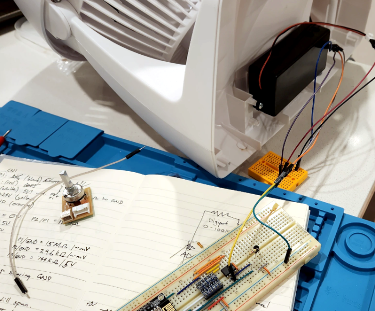
  • Controller: In the middle (with the pretty lights) is my DIY embedded controller. It reads the battery level and charging state from the MPPT and has a line that can remotely turn on and off the inverter. It decides when the inverter runs based on the battery charge level and available voltage. It also has a web interface so I can query the current status, adjust parameters, and manually override when it runs.

  • Ground: Not seen in the picture, there's grounding wire from the inverter's external ground screw to the server rack. The server rack is tied to the building's "earth ground". Proper grounding is essential for safety.
Everything is mounted vertically to a board that is hung from the side of the server rack. This allows me to easily take it down for any maintenance issues. (And when doing the initial testing, I could carry the entire thing outside.)

Even though I knew I'd be starting this project around March of this year, I started ordering supplies five months earlier (last November). This included solar panels, a solar charger, battery, and an inverter. I ordered other components as I realized I needed them. Why did I start this so early? I believed Trump when he said he would be imposing stiff tariffs, making everything more expensive. (In hindsight, this was a great decision. If I started ordering everything today, some items would cost nearly twice as much.)

Measuring Power

Before starting this project, I needed to understand how much power I'd require and how much it might save me on my utility bill.

As a software (not hardware) person, I'm definitely not an electrical engineer. For you non-electricians, there are three parts of electricity that need to be tracked:
  • Voltage (V). This is the amount of power supplied on the wires. Think of it like the pressure in a water pipe.

  • Amps (A). This is the amount of current available. Think of this like the size of the water pipe. A typical desktop computer may require a few amps of power. Your refrigerator probably uses around 20 amps when the compressor is running, while an IoT embedded device usually uses 200mA (milliamps, or 0.2A, that's flea power).

  • Watts (W). This is the amount of work available. W=AΓ—V.
These measurements are often compared to flowing water. Volts identify how fast a river is flowing (the water pressure). Amps identify how large the river is, and watts is the total energy delivered by the river. A wide but slow moving river has high amps but low voltage. A narrow but fast flowing river has a low current (low amps) but a high voltage. Because of the relationship between W, A, and V, the electronics can adjust the A and V distribution while mantaining the same W.

W, A, and V are instantaneous values. To measure over time, you typically see Watt-hours (Wh) and Amp-hours (Ah). Your utility bill usually specifies how many Wh you used (or kilowatts for 1000 Wh; kWh), while your battery will identify the amount of power it can store in terms of Ah at a given V. If you use fewer amps, then the battery will last longer.

Keep in mind, this can really screw up the power calculations if you get them wrong. For example, my 12V 100Ah DC battery is being converted to 120V AC power. If the AC uses a 1-amp load (like one server in the rack), then that's not 100 hours of battery; that's 10 hours. Why? 12V at 100Ah is 1200Wh. 1200Wh÷120V=10Ah, or 10 hours of power. (And with inverter's overhead and conversion loss, it's actually less.)

Parts and Parts

While I work with computers daily, I'm really a "software" specialist. Besides a few embedded systems, I don't do much with hardware. Moreover, the computer components that I deal with are typically low voltage DC (3.3V, 5V, or 12V and milliamps of power; it's hard to kill yourself if you briefly short out a 9V battery).

When it comes to high voltage, my electrical engineering friends all had the same advice:
  1. Don't kill yourself.

  2. Assume that all wires have enough power to kill you. Even when turned off.

  3. When possible, over-spec the components. If you need 5 amps, get something that can handle 10 amps. If you need 12 gauge wire (12awg), then use 8awg (a thicker wire). If you need 2 hours of power, get something that can provide 4 hours of power. You can never go wrong by over-spec'ing the components. (Not exactly true, but it's a really good heuristic.)
For the last year, I've been using some Shelly plugs to monitor the energy consumption of my server rack. Every hour I take a reading and store it in a database. I also wrote a web interface that can display the real-time information and graph the hourly usage. (Every vertical bar is an hour, and every color is one day.)


The lower part of the rack hosts FotoForensics, Hacker Factor, and my other primary services. It usually consumes about 230W of power, or 2A. (It can fluctuate up to almost 300W during a reboot or high load, but those don't last long.) The upper rack is for the development systems, and uses around 180W. (180W at 120V is 1.5A.) That's right, the entire rack is usually consuming less than 4Ah of power at any given time.

For this solar experiment, I decided to initially only power the upper rack with solar. (If it turns out to be really successful, then I might add in the lower rack's power needs.)

The Bad Experiences

I had a few bad experiences while getting this to work. I chalk all of them up to the learning curve.

Problem #1: The Battery
Setting up the MPPT, inverter, and ATS was easy. The battery, on the other hand, was problematic. There are lots of batteries available and the prices range wildly. I went with a LiFePO4 "deep cycle" battery because they last longer than typical lead acid and lithium batteries and are designed for repeatedly powering up and draining. LiFePO4 also doesn't have the "toxic fumes" or "runaway heat" problems that the other batteries often have.

I found a LiFePO4 battery on Amazon that said it was UL-1973 certified. (That means for use with a solar project.) However when it arrived, it didn't say "UL 1973" anywhere on the battery or manuals. I then checked with Underwriter Labs web site. The battery was not listed. The model was not listed. The brand was listed, but none of their products had UL certifications. This is a knock-off forgery of a battery. If they lied about their certification, then I'm not going to trust the battery.

Amazon said that the vendor handles returns directly. My first request to the vendor was answered quickly with an unrelated response. I wrote to them: "I'd like to return the battery since it is not UL certified, as stated on your product description page." The reply? "The bluetooth battery needs to be charged before you can use it." (This battery doesn't even have bluetooth!)

My second request to the vendor received no response at all.

I told my credit card company. They stopped payment, sent an inquiry to the vendor, and gave them 15 days to respond. Two weeks later, with no response, I was refunded the costs. The day after the credit card issued the refund, the vendor reached out to me. After a short exchange, they paid to have the battery returned to them.

The second battery that I ordered, from a different vendor, had all of the certificates that they claimed.

Problem #2: The Inverter
The first inverter that I got looked right. However, when I connected it to the ATS, the wall outlet's circuit breaker immediately tripped. Okay, that's really bad. (But also, really good that the circuit breaker did its job and I didn't die.) It turns out, inverters above a certain wattage are required to have a "neutral-ground bond". The typical American three-prong outlet has a hot, neutral, and ground wire. The N-G bond means that neutral and ground are tied together. This is a required safety feature. Every home and office circuit has exactly one N-G bond. (It's in the home or building's circuit breaker panel.)

The four-poll (4P) ATS ties all grounds together while it switches the hot and neutrals. The problem: If the inverter and wall outlet both have a N-G bond, then it creates a grounding loop. (That's bad and immediately trips the circuit breaker.) For most inverters, this functionality is either not documented or poorly documented. Some inverters have a built-in N-G bond, some have a floating neutral (no bond) and are expected to be used with an ATS, and some have a switch to enable/disable the N-G bond.

My first inverter didn't mention the N-G bond and it couldn't be disabled. Fortunately, I was able to replace it with one that has a switch. With the N-G bond safely disabled, I can use it with the ATS without tripping the circuit breaker.

Keep this in mind when looking for an inverter. Most of the ones I looked at don't mention how they are bonded (or unbonded).

Problem #3: The ATS
I spent days tracking down this problem. The ATS output goes to a big UPS. This way, any transfer delays or phase issues are cleaned up before reaching the computers. When the inverter turned on, I would see a variety of different problems:
  • Sometimes the UPS would run fine.

  • Sometimes the UPS would scream about an input problem, but still run off the input power.

  • Sometimes the UPS would not scream, and would slowly drain its internal battery while also using the inverter's power.

  • Sometimes the UPS would scream and refuse to use the input power, preferring to run off the UPS battery.
The problem was incredibly inconsistent.

If I removed the ATS, then the UPS had no problem running off utility power. If I moved the electrical plug manually to the inverter (with the N-G bond enabled), it also ran without any problems.

Long story short: Most automatic transfer switches have a "direction". If primary is utility and backup is the generator (or solar), then it demands to be installed in that direction. For my configuration, I want a battery-priority ATS, but most ATSs (including mine) are utility-priority. You cannot just swap the inputs to the ATS and have it work. If, like me, you swap them, then the results become incredibly inconsistent and will lead you down the wrong debugging path.

My solution? Someday I'll purchase a smart switch that is battery-priority. In the meantime, I have a Shelly smart-plug monitoring the utility power. My DIY smart controller tells the Shelly plug to turn on or off utility power. When it turns off, the ATS immediately switches over to using the inverter's power. And when my DIY controller see that the solar battery is getting low, it turns the utility grid back on.

The added benefit for my method of turning on or off the utility power is that I can control the switching delay. The inverter takes a few seconds to start up. I have a 15-second timer between turning on the inverter (letting it power up and normalize) and turning off the utility power. This seems to help the UPS accept the transfer faster.

Problem #4: Over-spec'd Inverter
Remember that advice I got? Always over-spec the equipment? Well, that's not always a good idea. As it turns out, a bigger inverter requires more energy to run (18Wh for a 2000W inverter vs 12Wh for a 1000W inverter). It also has a worse conversion rate for a low load. (The inverter claims to have >92% conversion rate, meaning that the 100Ah battery should last for 92Ah. But with a light load, it may be closer to 80%.)

I'll stick with the inverter that I got, but I could probably have used the next smaller model.

Problem #5: The Roof
I wanted to put the solar panels on the roof. I really thought this was going to be the easiest part. Boy, was I wrong.

There are federal, municipal, and local building requirements, and that means getting a permit. The city requires a formal report from a licensed structural engineer to testify that the roof can hold the solar panels. Keep in mind, I'm talking about two panels that weigh 14lbs (6kg) each. The inspector who goes up on the roof weighs more. If a big bird lands on my roof (we have huge Canadian geese), it weighs more. We get snow in the winter and the snow weighs more!

Unfortunately, the city made it clear that there is no waiver. I had earmarked $1000 for everything, from the panels to the battery, inverter, wires, fuses, mounting brackets, etc. I got quotes from multiple structural engineers -- they all wanted around $500. (There goes my budget!) And that's before paying for the permit. In effect, the project was no longer financially viable.

Fortunately, I found a workaround: awnings. The city says that you don't need a permit for awnings if they (1) are attached to an exterior wall, (2) require no external support, and (3) stick out less than 54 inches. My solar panels are mounted at an angle and act as an awning that sticks out 16 inches. (The mounts are so sturdy that I think they can hold my body weight.) No permit needed.

The awnings turned out to be great! They receive direct sunlight starting an hour after sunrise and it lasts until about 1pm in the summer. (It should get even more in the winter.) They continue generating power from ambient lighting until an hour before sundown. This is as good as having them on the roof!

The Scariest Part

High voltage scares me. (That's probably a healthy fear.) Connecting cables to the powered-off system doesn't bother me. But connecting wires to the big battery is dangerous.

Using rubber-gripped tools, I attached one cable. However, when I tried to connect the other cable, there was a big spark. It's a 100Ah battery, so that's expected. But it still scared the donuts out of me! I stopped all work and ordered some rubber electrical gloves. (Get rubber or nitrile, and make sure they are class 00 or higher.)

Along with the gloves, I ordered a huge on/off switch. This isn't your typical light switch. This monster can handle 24V at 275 amps! (It's good to over-spec.)

I connected the MPPT and inverter to one side of the switch. An 8awg cable that can handle 50 amps connects to the battery's negative pole. (Since the MPPT and inverter are both limited to 20 amps, the 50 amp cable shouldn't be a problem.)

With the gloves on, the switch powered off, and rubber-gripped tools in hand, I connected the switch to the battery. No zap or spark at all. Turning the switch on is easy and there is no spark or pop. This is the right way to do it.

Expected Savings

Without the solar project (just using the utility power), the server rack costs me about $35 per month in electricity to run.

I've been running some tests on the solar project's performance, and am very happy with the results.

Under theoretically ideal conditions, two 100W panels should generate a maximum of 200W. However, between power conversion loss, loss from cabling, and other factors, this theoretical maximum never happens. I was told to be happy if it generated a maximum of 150W. Well, I'm very happy because I've measured daily maximums between 170W and 180W received at the MPPT.

Fort Collins gets over 300 sunny days a year, so clear skies are the norm. With clear skies, the battery starts charging about 30 minutes after sunrise and gets direct (optimal) sunlight between 9am and 1pm. It generates an incredible amount of power -- the inverter drains the battery slower than the panels can charge it. For the rest of the afternoon, it slowly charges up the battery through indirect ambient light. The net result? It can run the upper half of the rack for over 10 hours.

This kind of makes sense:
  • The battery usually starts the day at about 50% capacity. It charges to 90% in under 2 hours of direct daylight.

  • In theory, I run the battery from 90% down to 20%. In practice, the battery usually hits 100% charged during the morning because if charges faster than it drains. It doesn't start running below 100% until the afternoon. (That's wasted power! I need to turn on more computers!)

  • I'm only using the upper rack right now (1.5Ah, 180Wh). The inverter consumes another 18W, so call it 200W of power. Assume a fully-charged 1200Wh battery with 920Wh available, draining at a rate of 200Wh. It should last about 4.5 hours. If I power the entire rack, it will be closer to 2 hours. And in either case, that countdown only starts when it's running off of battery in the late afternoon.
We had one dark and stormy day, and one very overcast day so far. In both instances, it took most of the morning to charge the battery, but it still managed to run the upper rack for a few hours. Fort Collins has "surge pricing" for electricity. In the summer, than means 2pm to 7pm has the most expensive power (about 3x more than non-surge times). Fortunately, the batteries keep the rack running during much of that expensive period.

I'm aiming to use the battery during the surge pricing period. If I ran the numbers correctly, the server might reduce my $35/month cost by $20-$25/month. At that rate, it will pay off the $1000 investment in under 4.5 years. If we have a lot of bad weather, then it might end up being 5 years. The batteries and panels will need to be replaced in 8-10 years, so as long as it pays off before then, I'll be in the profit range.

As self-paced learning goes, I don't recommend high voltage as an introductory project. Having said that, I really feel like I've learned a lot from this experiment. And who knows? Maybe next time I'll try wind power. Fort Collins has lots of windy days!

Top 6 Threat Discoveries of 2018

By: Radware

Over the course of 2018, Radware’s Emergency Response Team (ERT) identified several cyberattacks and security threats across the globe. Below is a round-up of our top discoveries from the past year. For more detailed information on each attack, please visit DDoS Warriors. DemonBot Radware’s Threat Research Center has been monitoring and tracking a malicious agent […]

The post Top 6 Threat Discoveries of 2018 appeared first on Radware Blog.

New Threat Landscape Gives Birth to New Way of Handling Cyber Security

With the growing online availability of attack tools and services, the pool of possible attacks is larger than ever. Let’s face it, getting ready for the next cyber-attack is the new normal! This β€˜readiness’ is a new organizational tax on nearly every employed individual throughout the world. Amazingly enough, attackers have reached a level of […]

The post New Threat Landscape Gives Birth to New Way of Handling Cyber Security appeared first on Radware Blog.

Cybersecurity in 2023

By: seo_spec

Companies are beginning to realize that the location of their employees and the devices they use are not as important as they used to be. The work culture will be more about what you do and not where you do it. In 2023, a hybrid world begins to develop where the barriers of the digital and real world will disappear. With flexibility being a priority for businesses and ordinary users, they face the challenge of user security and privacy as they easily change their location with multiple devices and networks and use different communication platforms. One of the most important trends that will dominate in 2023 is political or social attacks and state-sponsored cyberattacks. Political attacks can quickly damage businesses, industries, and economies, as well as cause unrest in a region.

The cloud platform and the Zero Trust method are the perfect combination to increase the security of access to every user and device, regardless of their local location. In 2023, this cybersecurity method will be actively implemented.

Clive Harby said in 2006 that this data is the new oil, but it is now routinely shared by vendors, customers and businesses. Zero Trust’s main goal is to protect this strategic asset from falling into the wrong hands.

As the use of artificial intelligence and machine learning evolve, we’re seeing new cybersecurity solutions emerge more often and help identify and respond to threats in real time. Such technologies will help organizations find and avoid attacks. Many expect technology to facilitate faster and more accurate responses to possible threats as the threat landscape evolves.

The emergence of quantum-type computers also indicates that the vulnerability of traditional forms of encryption is increasing. As a result, researchers have developed new quantum-resistant forms of security that can protect advanced computing systems. These new technologies will be crucial to securing sensitive information and methods over the coming years.

Companies, too, are beginning to view blockchain as something more than cryptocurrency. Blockchain is expected to be used to create new, innovative solutions to protect cyberspace. For example, blockchain systems can provide more secure verification of a user’s identity, and blockchain-based data stores can help protect against data leakage.

As the threat continues to grow, government and regulators are setting requirements for organizations to create appropriate cyber defenses. In 2023, expect an increased focus on cybersecurity regulation and compliance and the implementation of new requirements and guidelines to help organizations protect their system data.

As more and more devices connect to the Internet, IoT devices are becoming a serious problem. As a result, new technology is being developed to protect IoT devices from manipulation. This will be especially important in healthcare, where the security of medical devices is important.

In 2023, cyber threats will emerge in a new world, and many companies will actively use the latest technology to provide cyber protection. As a result, it is safe to assume that this trend and development will play an important role in strengthening information security in general.

❌